Weight secured by expansion element in golf club shaft

a golf club shaft and expansion element technology, applied in the field of golf club counterweighting, to achieve the effect of easy installation and easy incorporation into golf clubs

Inactive Publication Date: 2017-10-26
JOHNSON JOHN
View PDF0 Cites 1 Cited by
  • Summary
  • Abstract
  • Description
  • Claims
  • Application Information

AI Technical Summary

Benefits of technology

[0014]It is a primary object of the present invention to provide an improved expansion / friction type weight assembly implementation that fulfills the above-described unfulfilled need, including structure that engages the weight assembly positively for upward adjustment or removal, and that can be readily and easily incorporated into golf clubs at original manufacture as well as in the aftermarket and user golf play.SUMMARY OF THE INVENTION
[0015]The foregoing object has been met by the disclosed golf club counter-weighting system, viable for original manufacture, after-marketing and user golf play, featuring an expandable weight assembly that is easily installed at a designated location within a golf club shaft and expanded via a user expansion tool so as to become reliably secured in place by frictional pressure against the surrounding shaft. In a primary embodiment, the weight assembly is made to be threadedly engagable by the opposite end of a dual-function user tool that enables the weight assembly, when unexpanded, to be conveniently moved axially for initial installation, relocation and / or removal.

Problems solved by technology

Category 2: securing the weight assembly using friction applied against the interior surface of the golf club shaft, either by (a) one or more expansion elements attached to (or constituting) weight elements, typically requiring special tools for installation, location adjustment and removal, (b) specialized resilient sleeves on weight elements, or (c) a specialized resilient lining on the shaft interior surface; however subcategories (b) and (c) present challenging difficulties due to the conflicting requirements of providing both the compressive holding force for reliable frictional axial retention while also enabling convenient axial adjustment and trouble-free removal or readjustment if required, and furthermore accommodating the diameter variations in tapered shafts.

Method used


Image

  • Weight secured by expansion element in golf club shaft
  • Weight secured by expansion element in golf club shaft
  • Weight secured by expansion element in golf club shaft

Examples


Embodiment Construction

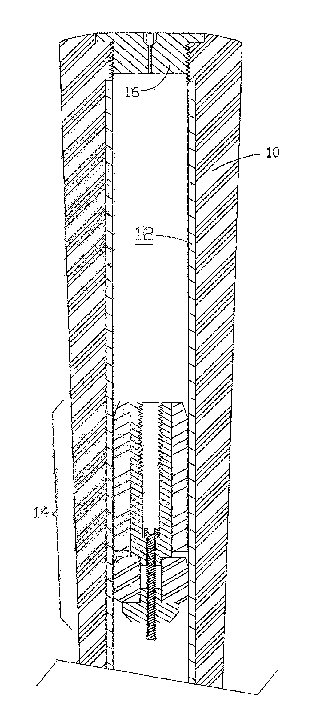
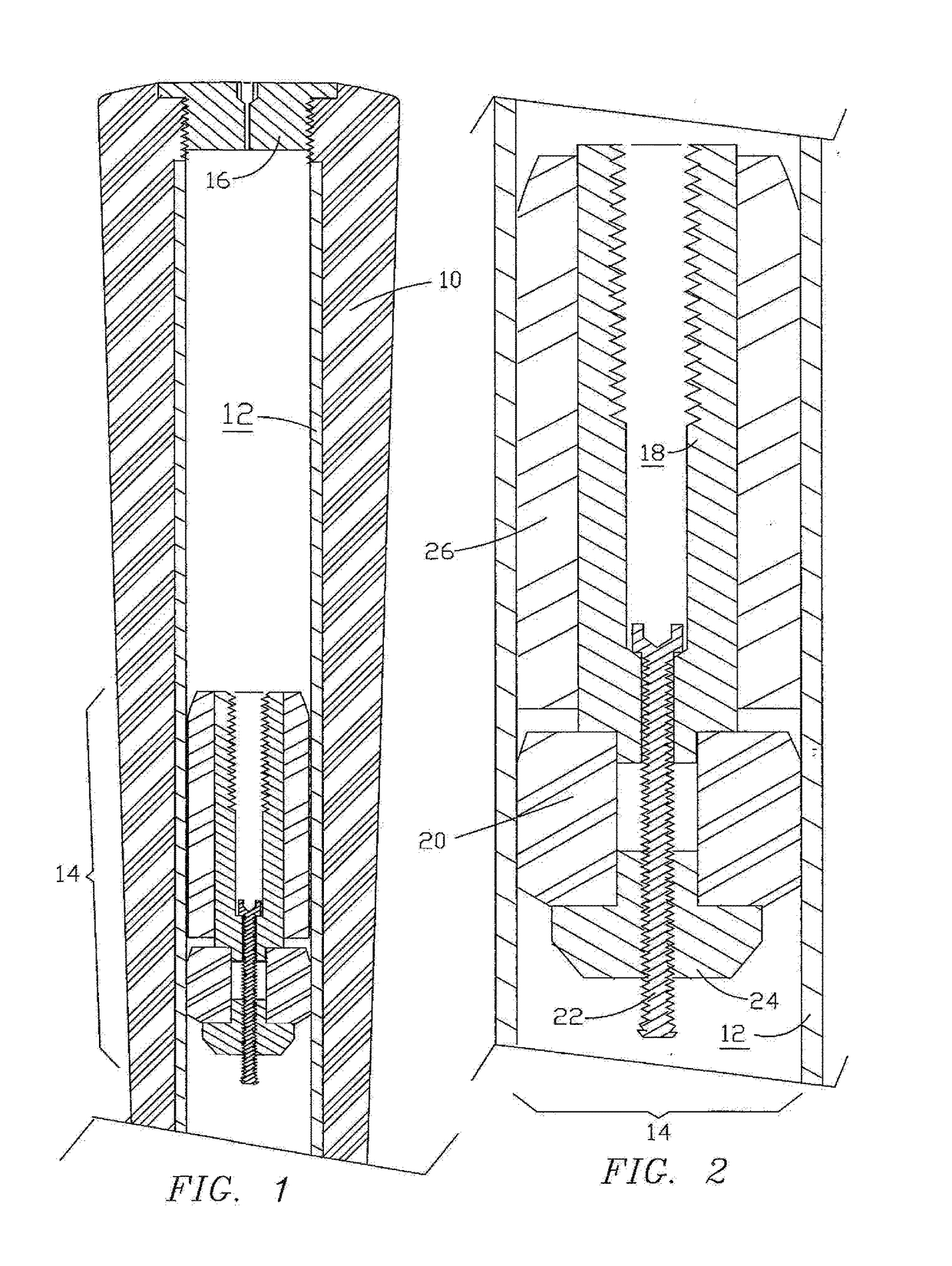
[0026]FIG. 1 is a cross-sectional elevation of an upper portion of a golf club having a grip 10 fitted onto a shaft 12 within which a weight assembly 14 of the present invention has been installed and secured at the selected axial location shown. A removable cap 16 in the top of grip 10 is fitted into a central opening in grip 10 sized to allow insertion and installation of weight assembly 14. Typically cap 16 is configured at top center with a driving recess and traversed there by a small vent passageway as shown.

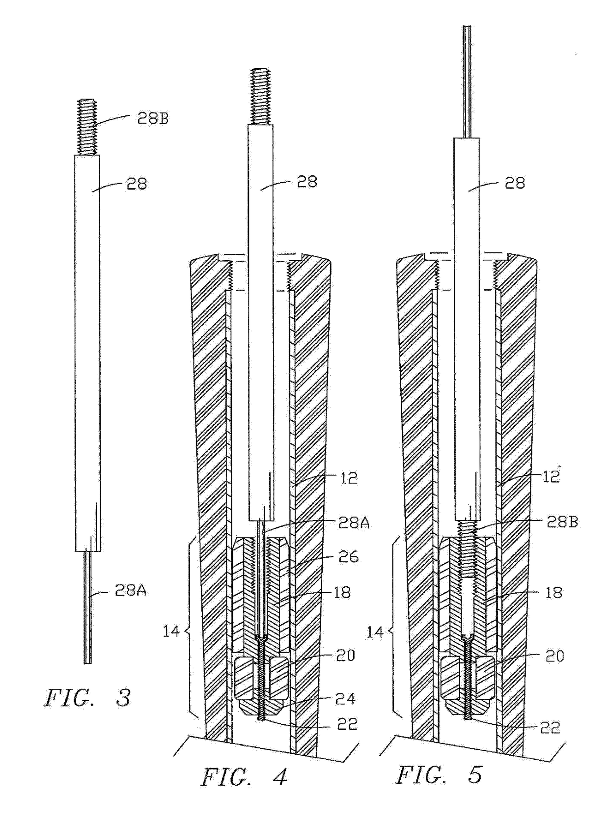
[0027]FIG. 2 is an enlargement of a portion of FIG. 1 showing a resilient expansion element 20 expanded and thus frictionally securing the weight assembly 14 to the surrounding portion of shaft 12. In weight assembly 14, a metal weight element 18 is coupled onto and drawn against expansion element 20 by a machine screw 22 threadedly engaging an annular pressure plate 24, in the form of an inverted T-nut, bearing against the bottom side of expansion element 20. As shown, sc...


PUM


Abstract

A golf club counter-weighting system, viable for both original manufacture and after-marketing, features an expandable weight assembly that is easily installed at a designated location within a golf club shaft and expanded via a user tool so as to become reliably secured in place by frictional pressure against the surrounding shaft. In a primary embodiment, the weight assembly is made to be threadedly engagable by the opposite end of a dual-function user tool enabling the weight assembly, when unexpanded, to be conveniently moved axially for initial installation, relocation and / or removal.

Description

FIELD OF THE INVENTION[0001]The present invention relates to the field of sports equipment, and more particularly to golf club counter-weighting for improving a golfer's playing and score by more optimally matching the golf club to the dynamic physical characteristics of the individual golfer, by adding a weighting assembly secured at a designated location in a hollow shaft of golf club.BACKGROUND OF THE INVENTION[0002]There has been an evolution in golf club technology that has led to ultra light-weight thin-wall hollow shafts. These have intensified concern about optimally matching the amount of mass, including its location and distribution in the golf club, to the physical characteristics of the individual golfer, considering swing dynamics.[0003]Along with attention that has been given to optimizing the mass at the club head end for the lightweight shaft, there has been recognition that better control, distance and accuracy can be obtained by counterbalancing the mass of the clu...

Claims


Application Information

Patent Timeline
Patent Type & Authority Applications(United States)
IPC IPC(8): A63B60/24A63B53/14A63B60/54
CPCA63B60/24A63B60/54A63B53/14A63B60/16A63B60/50
Inventor JOHNSON, JOHN
Owner JOHNSON JOHN
Why Eureka
Try Eureka