

Power supply device for electric vehicle
a technology for power supply devices and electric vehicles, applied in electric devices, vehicle sub-unit features, propulsion parts, etc., can solve the problems of promoting degradation of main batteries and deficiency of cooling capability of coolers, and achieve the effect of suppressing degradation of primary electric storage devices and enhancing charging efficiency of secondary electric storage devices
- Summary
- Abstract
- Description
- Claims
- Application Information
AI Technical Summary
Benefits of technology
Problems solved by technology
Method used
Image

Examples
embodiment 1
[0091]As described above, in Embodiment 1, when the cooling fan of the cooler 15 is driven at the target rotation speed RT, the SOC of the auxiliary battery 70 is limited to the range SOCL to SOCH less than 100% and it is thus possible to increase the charging efficiency of the auxiliary battery 70 and to improve the fuel efficiency FC.
[0092]When the cooling fan is not driven at the target rotation speed RT, the SOC of the auxiliary battery 70 is 100% and it is thus possible to enhance the cooling capability of the cooler 15 to delay the degradation of the main battery 10.
[0093]In Embodiment 1, the main DC / DC converter 60 is controlled such that the SOC of the auxiliary battery 70 is in the predetermined range SOCL to SOCH less than 100% in the first charging mode M1, but the invention is not limited to this embodiment. The main DC / DC converter 60 may be controlled such that the SOC of the auxiliary battery 70 is equal to a predetermined target value (for example, a median value bet...
embodiment 2
[0099]That is, since the SOC of the auxiliary battery 70 varies mainly depending on the voltage across terminals Vs, the SOC of the auxiliary battery 70 can be approximated with the voltage across terminals Vs. Accordingly, in Embodiment 2, the voltage across terminals Vs is detected as the approximate value of the SOC of the auxiliary battery 70, and the charging mode is switched between a first charging mode M1 in which the voltage Vs of the auxiliary battery 70 is set to the range between a lower limit VD lower than a rated voltage VR and an upper limit VU and a second charging mode M2 in which the voltage Vs of the auxiliary battery 70 is set to the rated voltage VR.
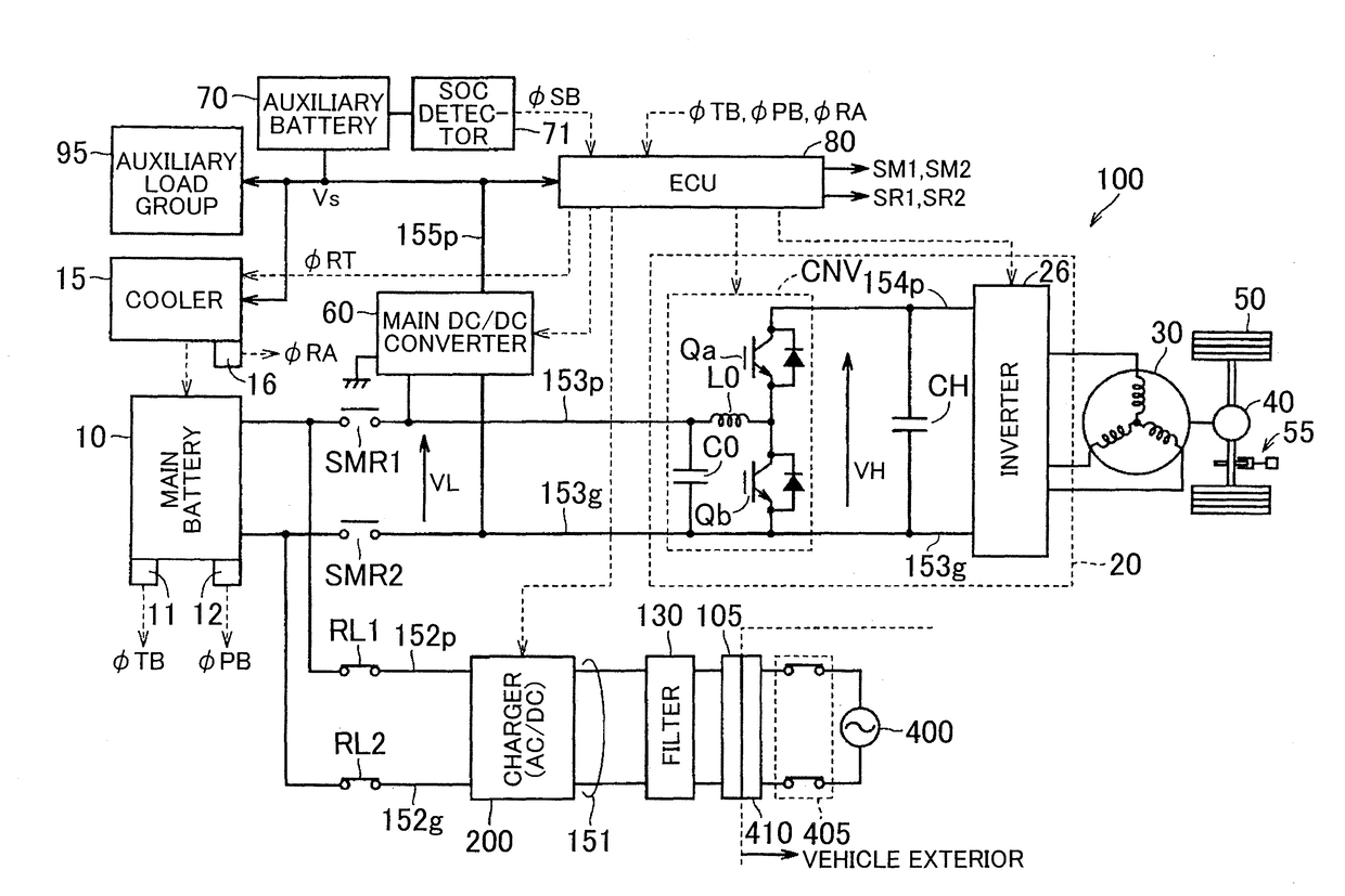
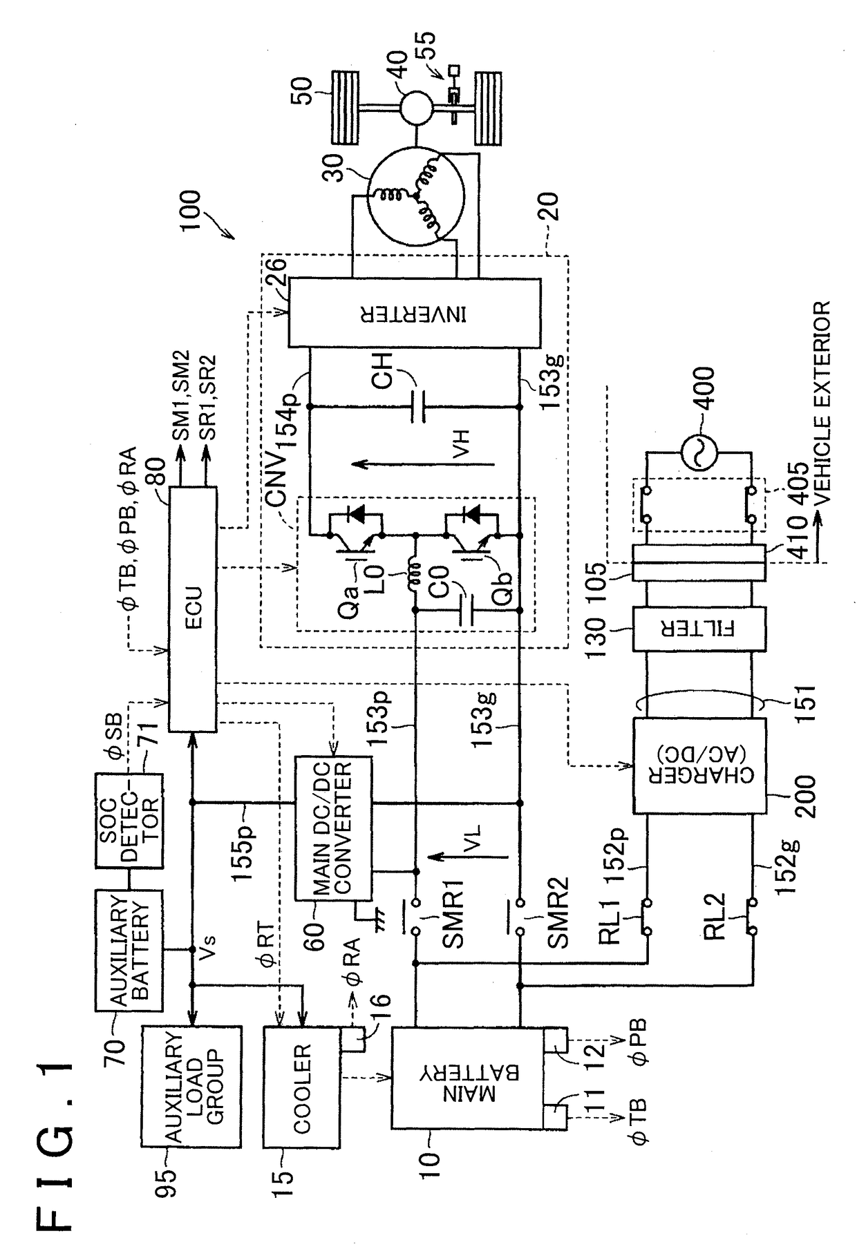
[0100]FIG. 5 is a circuit block diagram illustrating a configuration of an electric vehicle 101 according to Embodiment 2 of the invention, and corresponds to FIG. 1. Referring to FIG. 5, the electric vehicle 101 is different from the electric vehicle 100 illustrated in FIG. 1, in that the SOC detector 71 is replaced...
embodiment 3
[0119]That is, as can be seen from FIGS. 3A, 4A, when the target rotation speed RT is equal to or greater than a certain value (this value is defined as a second threshold rotation speed RTh2) in the first charging mode M1, the actual rotation speed RA does not follow the target rotation speed RT. Accordingly, in Embodiment 3, the charging mode is switched from the first charging mode M1 to the second charging mode M2 when RT≧Rth2 is established.
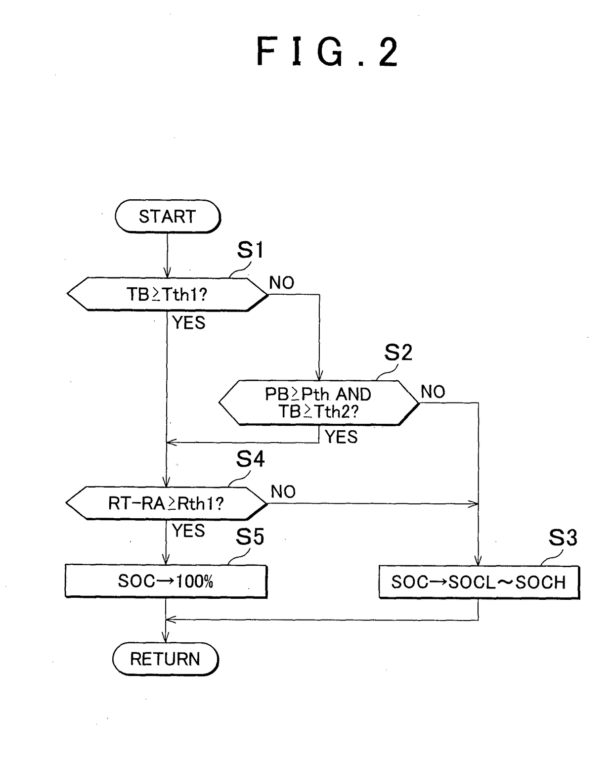
[0120]FIG. 12 is a flowchart illustrating an operation of an electric vehicle according to Embodiment 3 and corresponds to FIG. 2. The flowchart illustrated in FIG. 12 is different from the flowchart illustrated in FIG. 2, in that step S4 is replaced with step S4A. in step S4A, the ECU 80 determines whether RT≧Rth2 is established, sets the SOC of the auxiliary battery 70 to 100% in step S5 when RT≧Rth2 is established, and sets the SOC of the auxiliary battery 70 to 100% in step S3 when RT≧Rth2 is not established.
[0121]FIGS. 13A to 13C are ti...
PUM
 Abstract
Description
Claims
Application Information