Encoder and robot

Active Publication Date: 2017-10-26
SEIKO EPSON CORP
View PDF1 Cites 5 Cited by
  • Summary
  • Abstract
  • Description
  • Claims
  • Application Information

AI Technical Summary

Benefits of technology

The invention provides an encoder that can improve detection accuracy, which is useful for a robot that uses the encoder.

Problems solved by technology

In the encoder unit described in WO 2013 / 065737, in which the polarization layer is provided between each of the optical sensors and the polarizer on the optical scale, the amount of light received with each of the optical sensors decreases, resulting in a problem of a decrease in detection accuracy.

Method used


Image

  • Encoder and robot
  • Encoder and robot
  • Encoder and robot

Examples


first embodiment

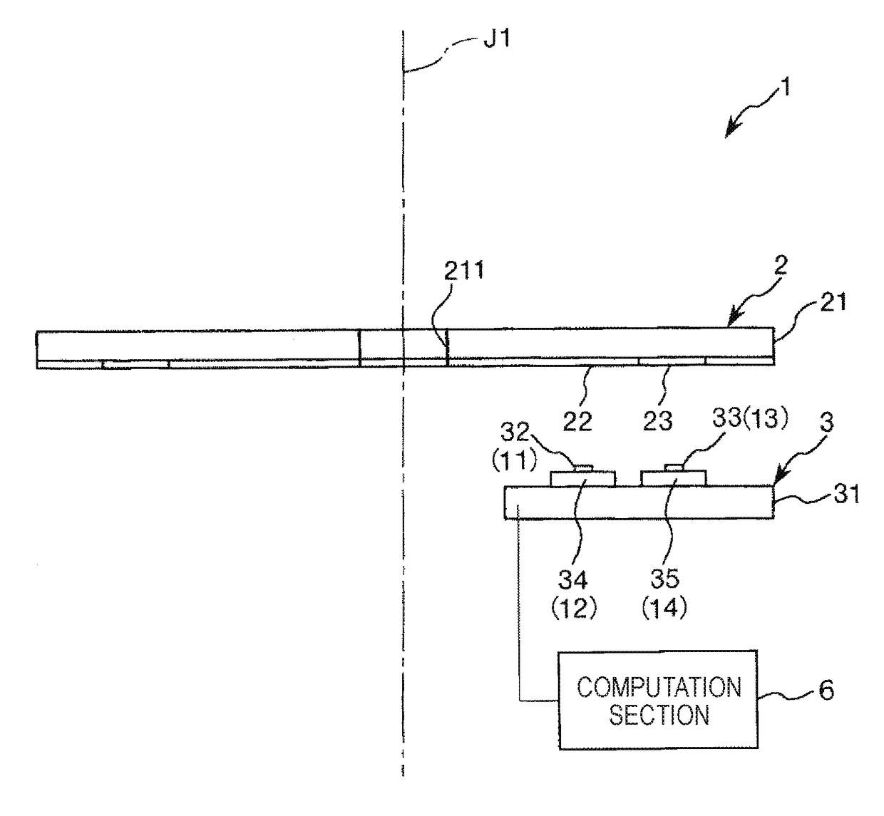
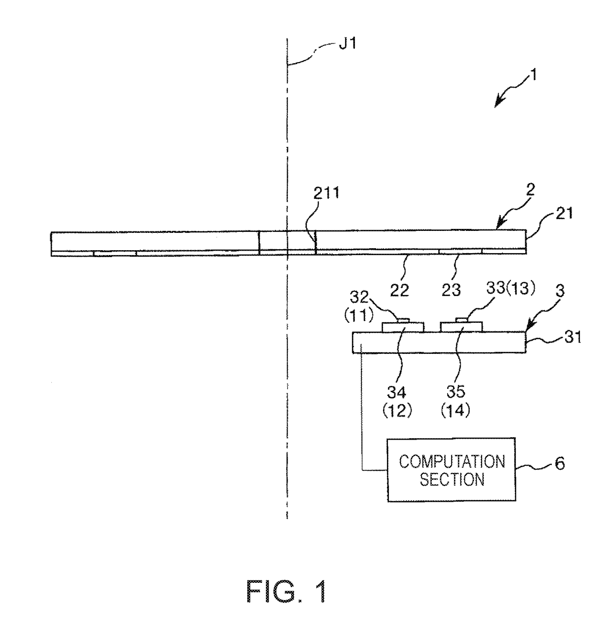
[0051]FIG. 1 is a diagrammatic view for describing an encoder according to a first embodiment of the invention.

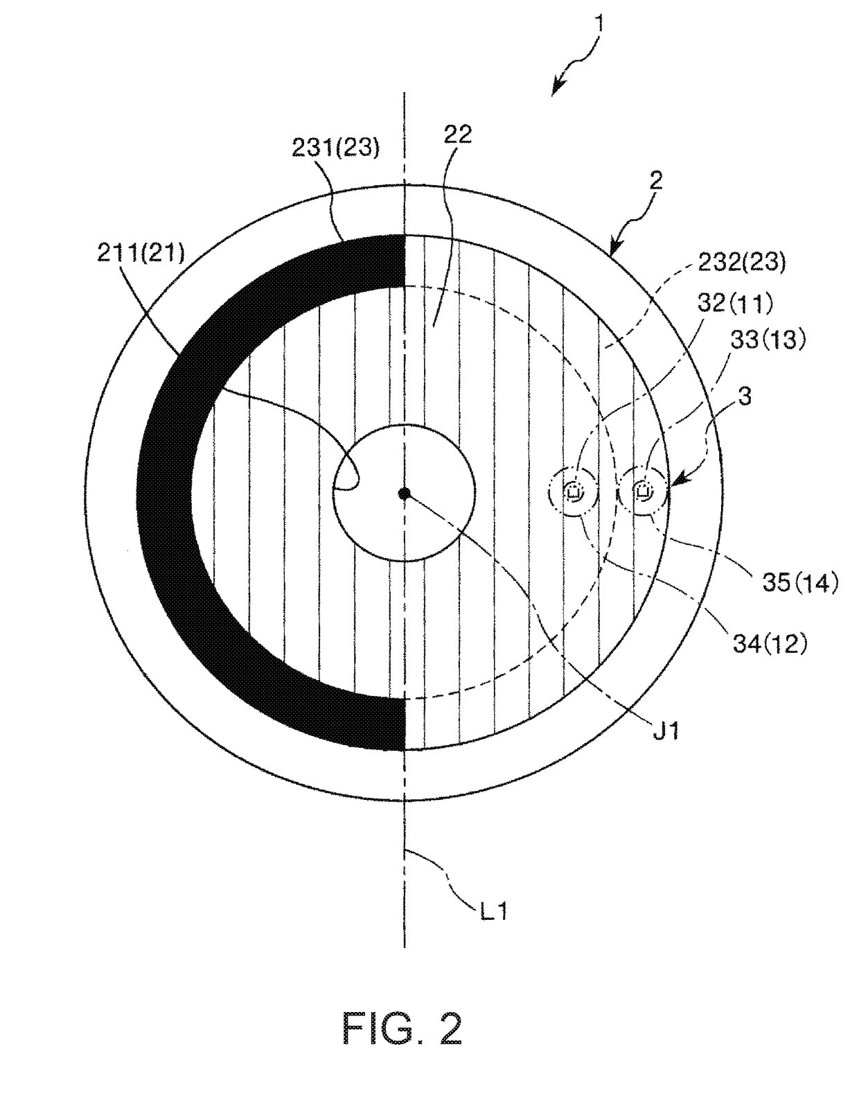
[0052]An encoder 1 shown in FIG. 1 is a reflective, optical rotary encoder. The encoder 1 includes an optical scale 2, which pivots around a pivotal axis J1, a sensor unit 3, which is so stationarily disposed as to face the optical scale 2, and a computation section 6, which is electrically connected to the sensor unit 3.

[0053]The optical scale 2 includes a substrate 21 and further includes a polarizing portion 22 and a 180° determination track 23, which are provided on one surface of the substrate 21. The sensor unit 3 includes a substrate 31 and further includes light emitting devices 32, 33 and light receiving devices 34, 35, which are provided on the substrate 31 and on the side thereof facing the optical scale 2. The light emitting device 32 forms a light outputting portion 11 (first light outputting portion), and the light receiving device 34 forms a light detecting p...

second embodiment

[0113]FIG. 8 is a plan view showing an encoder according to a second embodiment of the invention. FIG. 9 is a plan view for describing light outputting portions and light detecting portions provided in the encoder shown in FIG. 8. FIG. 10 shows graphs illustrating the relationship between the rotational angle of an optical scale and outputs (current values) from the light detecting portions in the encoder shown in FIG. 8.

[0114]In the following description of the second embodiment, differences from the embodiment described above will be primarily described, and the same items will not be described. In FIGS. 8 and 9, the same configurations as those in the embodiment described above have the same reference characters.

[0115]The present embodiment is the same as the first embodiment described above except that the light outputting portions and the light detecting portions are differently configured.

[0116]A sensor unit 3A provided in an encoder 1A shown in FIG. 8 is disposed on the far s...

third embodiment

[0121]FIG. 11 is a plan view showing an encoder according to a third embodiment of the invention.

[0122]In the following description of the third embodiment, differences from the embodiments described above will be primarily described, and the same items will not be described. In FIG. 11, the same configurations as those in the embodiments described above have the same reference characters.

[0123]The present embodiment is the same as the first embodiment described above except that the light outputting portions and the light detecting portions are differently configured. In particular, the present embodiment is the same as the second embodiment described above except that the second light emitting device and the second light receiving device are arranged differently.

[0124]A sensor unit 3B provided in an encoder 1B shown in FIG. 11 is disposed on the far side of the plane of FIG. 11 with respect to the optical scale 2 and includes the light emitting devices 32, 33, and 36 and the light...


PUM


Abstract

An encoder includes an optical scale that is so provided as to be pivotable around a pivotal axis and includes a polarizing portion having a polarization characteristic, a light outputting portion that outputs linearly polarized light toward the polarizing portion, and a light detecting portion that detects the linearly polarized light from the optical scale. The light outputting portion includes a vertical cavity surface emitting laser, and light emitted from the vertical cavity surface emitting laser spreads at an angle greater than or equal to 5° but smaller than or equal to 20°.

Description

BACKGROUND1. Technical Field[0001]The present invention relates to an encoder and a robot.2. Related Art[0002]As one kind of encoder, an optical rotary encoder is typically known (see WO 2013 / 065737, for example). A rotary encoder is used, for example, in a robot including a robot arm having a pivotable joint and detects the rotational angle, the rotational position, the number of revolutions, the rotational speed, and other pivotal states of the joint.[0003]For example, the encoder unit described according to WO 2013 / 065737 includes an optical scale and an optical sensor package. The optical scale has a polarizer rotatable around the center thereof. The optical sensor package has two optical sensors that are 180° symmetrically positioned with respect to the center of the polarizer and face the polarizer. A polarization layer is provided between each of the optical sensors and the polarizer, and the polarization layer extracts, from light incident on the optical sensor, light polari...

Claims


Application Information

Patent Timeline
IPC IPC(8): G01D5/347B25J13/08H01S5/183
CPCG01D5/3473B25J13/088G01D5/34776H01S5/183G01D5/345H01S5/0264H01S5/04252H01S5/04254H01S5/04256H01S5/18311H01S5/18355H01S5/34313H01S5/423H01S2301/176
Inventor TOMIOKA, HIROTONISHIDA, TETSUO
Owner SEIKO EPSON CORP
Why Eureka
Try Eureka