Flow measurement device for measuring flow rate and flow velocity
Inactive Publication Date: 2002-09-19
NGK SPARK PLUG CO LTD
View PDF0 Cites 11 Cited by
Summary
Abstract
Description
Claims
Application Information
AI Technical Summary
This helps you quickly interpret patents by identifying the three key elements:
Problems solved by technology
Method used
Benefits of technology
Benefits of technology
[0008] It is therefore an object of the invention to provide a flow measurement device, which is easy to manufacture and has excellent detection accuracy.
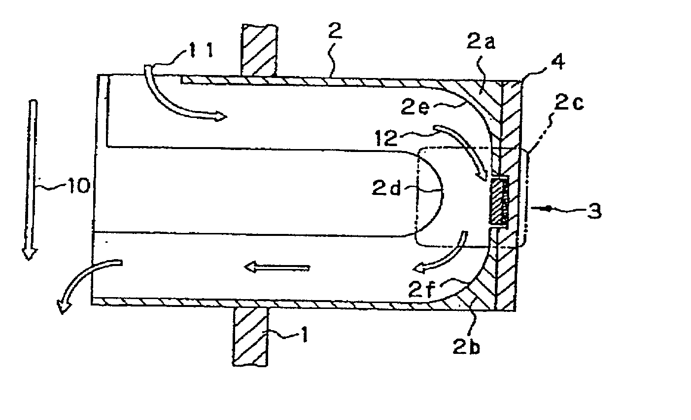
[0009] A flow measurement device of a first aspect of the invention has means, provided so as to act on a flow in a divided flow pipe, for forming such a flow as to obliquely impinge against a detection face of a flow-detection element, as schematically shown in FIG. 1(A) wherein a flow 12 is shown by a upper arrow slanting against the detection element face. In order to obliquely impinge the flow against the detection element, a flow passage or inner diameter of the divided flow pipe is reduced so as to form a passage-narrowest portion and in addition the pipe is bent at the passage-narrowest portion so as to form a inverted arc whereat the detection element is placed. In this structure, a flow speed maximizes at the passage-narrowest portion and a flow of an object such as a gas impinges obliquely on the element. A better performance of the flow measurement device is attained when an upstream flow passage and a downstream passage along the inverted arc wherein the detection element is placed in a middle is shaped in symmetry along the inverted arc, according to one of the aspects of the invention.
[0010] It is considered that, by this flow control means, a flow to be detected is constantly supplied to the detection face of the detection element and it follows that the flow to be detected surely flows on the detection face. In addition, it is considered as an advantage that generation of a vortex flow and exfoliation in the vicinity of the detection face are suppressed so that flow detection accuracy and flow detection reproducibility are improved.
Problems solved by technology
This is because even if a smallest displacement owing, for example, to a bonding layer unevenly applied exists, it follows that a vortex flow and exfoliation region is generated, and the vortex flow and exfoliation region exerts an adverse effect on a heat extraction of the measurement resistor especially at the surface of the sensor element, so that a measurement result becomes erroneous".
However, in order to "bond a surface of the sensor element into the notch such that it becomes, as far as possible, the same face as a surface of the sensor support body" as proposed in Japanese patent application laid-open No. 9-503311, there is a problem in that a high and precise manufacturing technique is required and manufacturing efficiency is thereby decreased.
Further, in order to assure that the surface of the sensor element is the same face as the surface of the sensor support body, a further problem arises in that a precise inspection is necessary.
Method used
Image
Click on the blue label to locate the original text in one second.
Reading with bidirectional positioning of images and text.
Examples
embodiment 1
[0065] Embodiment 1
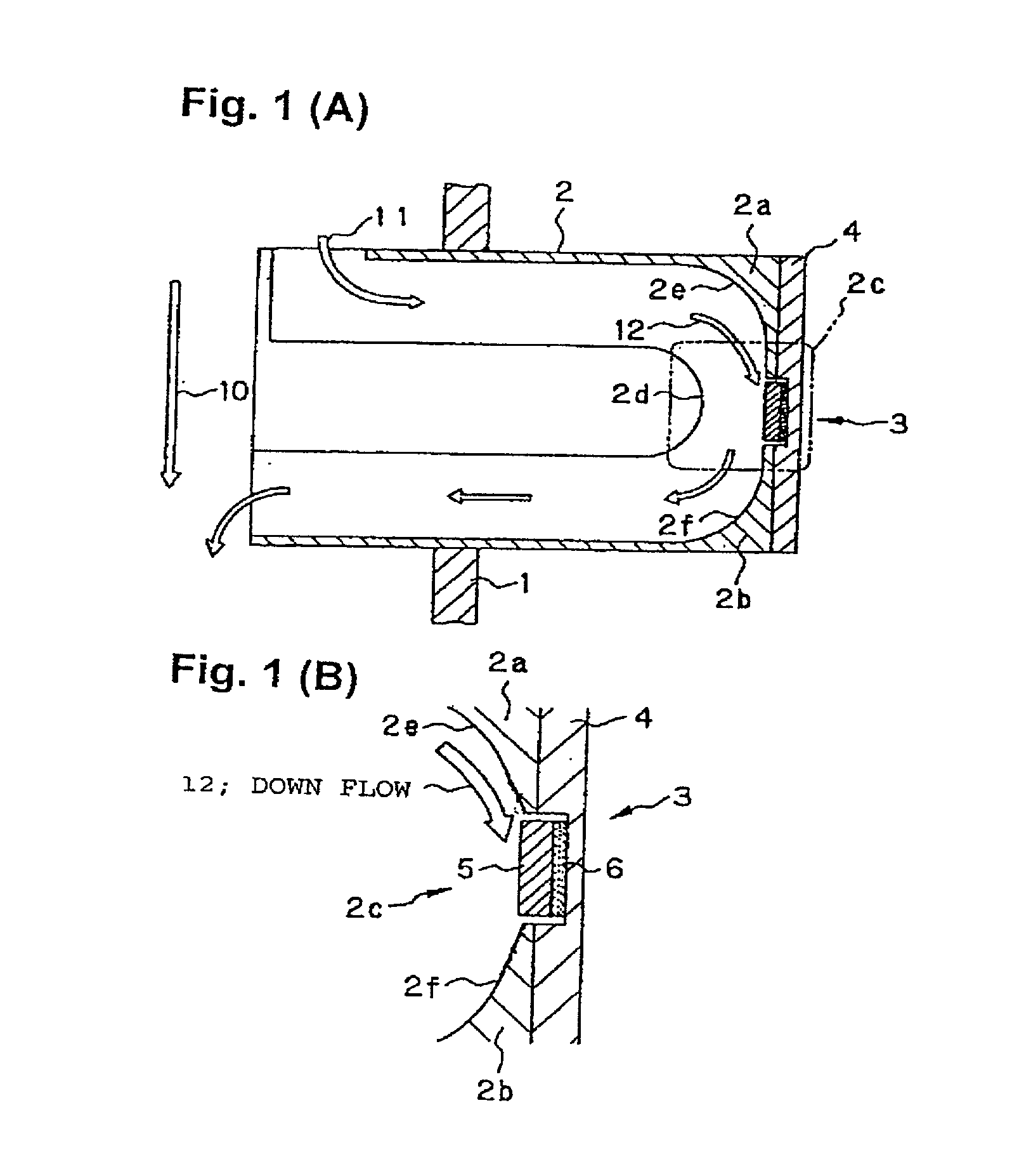
[0066] FIG. 1(A) and FIG. 1(B) are explanatory views of a measurement device of an Embodiment 1 of the invention, wherein FIG. 1(A) is an explanatory view schematically showing a longitudinal sectional view of a divided flow pipe, and FIG. 1(B) an enlarged view in the vicinity of a detection portion. Referring to FIG. 1(A) and FIG. 1(B), in this measurement device, a divided flow pipe 2 is attached to a main flow pipe 1 so as to be basically orthogonal. A flow in the main flow pipe 1, which is a detection object, is introduced into the divided flow pipe 2.
[0067] The divided flow pipe 2 is curved such that the flow taken into the divided flow pipe 2 can be inverted. The divided flow pipe 2 has two mutually parallel straight flow portions extending in a direction approximately orthogonal to a flow 10 in the main flow pipe 1 where the divided flow pipe 2 is attached to the main flow pipe 1, a curved portion 2c for connecting the two strait flow portions (straight flo...
embodiment 2
[0082] Embodiment 2
[0083] Next, as the measurement device of Embodiment 2 of the invention, an example is explained using the divided flow pipe having a structure in which a flow sectional diameter changes besides the structure possessed by the divided flow pipe in Embodiment 1. Therefore, in order to avoid a repetition in the following explanation, the device according to Embodiment 2 is explained mainly about portions different from the Embodiment 1 and as to the similar portions, the descriptions relating to Embodiment 1 are suitably applied to Embodiment 2.
[0084] FIG. 4 is an explanatory view of the measurement device of Embodiment 2 of the invention, and it schematically shows a longitudinal sectional view of the divided flow pipe. Referring to FIG. 4, a divided flow pipe 42 in this flow rate measurement device has, at its upstream side straight flow portion, a portion whose flow sectional diameter is reduced or throttled along a flow direction (hereafter, this is referred to a...
embodiment 3
[0106] Embodiment 3
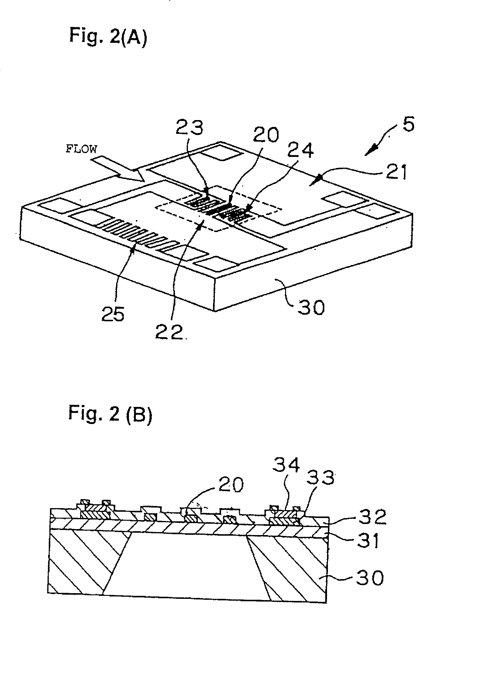
[0107] As Embodiment 3 of the invention, various shapes of the detection element applied to the measurement device according to the invention are explained. FIG. 8(A) to FIG. 8(C) relate to Embodiment 3 of the invention, and are explanatory views of the various shapes of the detection element applied to a flow rate measurement device according to the invention, wherein respectively the upper drawing is a plan view and the lower drawing is a sectional view of a plane center portion.
[0108] The detection element shown in FIG. 8(A) is a square type similar to the detection element used in Embodiments 1 and 2, and a diaphragm portion 50 is provided in a center portion of the square. The detection element shown in FIG. 8(B) is a rectangle type, and a diaphragm 51 is provided in an end portion of the rectangle. Further, the detection element shown in FIG. 8(C) is also a rectangle type, and a diaphragm portion 52 is provided in a center portion of the rectangle.
PUM
Abstract
A flow rate and flow velocity measurement device. A part of a flow 10 in a main flow pipe 1, which is a detection object, is introduced into a passage of a divided flow pipe 2 and becomes a flow 11. The divided flow pipe 2 has a curved portion 2c or rather an inverted arc portion in which the flow is abruptly changed in direction or rather inverted by protuberances 2a, 2b formed preferably in symmetry in upstream and downstream sides of the curved portion 2c. Outside the main flow pipe 1, there is disposed on the bottom portion of the curved portion 2c of the divided flow pipe 2 a detection element 5 fixed to a support body 4 while protruding preferably 0.05-0.3 mm from flow passage faces 2e, 2f in the vicinity thereof. An opposed face 2d opposite to the detection element 5 protrudes toward the detection face so as to throttle the passage and to accelerate a flow speed at the element. Thus, in the curved portion 2c from the flow 11, a down flow 12 is constantly formed obliquely impinging against the detection face of the detection element 5, improving flow measurement accuracy within a wide flow speed range.
Description
BACKGROUND OF THE INVENTION[0001] 1. Field of the Invention[0002] The present invention relates to a device for measuring various quantities concerning a flow, among others, relates to a flow rate and flow velocity measurement device using a detection element integrally formed on a support body and / or a temperature sensitivesemiconductorchip, and relates to a measurement device suitably applied, for example, as a combustion controlling mass flow rate sensor of an engine for a vehicle or industry, or a mass flow rate sensor for an industrial air conditioningsystem and compressor pressurized air supply system and, furthermore, an air / fuel ratio controlling flow rate sensor of a domestic gas hotplate.[0003] 2. Description of the Related Art[0004] Japanese patent application laid-open No. 9-503311 proposes "A sensor support body for a device measuring an intake of internal combustion engine, provided with a sensor support body and a sensor element on a plate inserted into a flow rate...
Claims
Application Information
Patent Timeline
Application Date:The date an application was filed.
Publication Date:The date a patent or application was officially published.
First Publication Date:The earliest publication date of a patent with the same application number.
Issue Date:Publication date of the patent grant document.
PCT Entry Date:The Entry date of PCT National Phase.
Estimated Expiry Date:The statutory expiry date of a patent right according to the Patent Law, and it is the longest term of protection that the patent right can achieve without the termination of the patent right due to other reasons(Term extension factor has been taken into account ).
Invalid Date:Actual expiry date is based on effective date or publication date of legal transaction data of invalid patent.

