Subsea Valve, Flow System and Method of Use

Inactive Publication Date: 2017-10-26
ENERMECH
View PDF0 Cites 3 Cited by
  • Summary
  • Abstract
  • Description
  • Claims
  • Application Information

AI Technical Summary

Benefits of technology

[0016]One aim of the invention is to provide subsea flooding apparatus and/or a subsea valve which is relatively lightweight, small, and/or low in bulk compared to prior art subsea flooding apparatus and/or subsea valves.
[0017]Another aim of the invention is to provide an apparatus and flow system which is relatively simple to d

Problems solved by technology

The differential pressure will have the tendency to cause excessive flow to pass through the pump and tends to collapse equipment and connections to the pipeline once the pipeline valve is opened for flooding and pigging.
Furthermore, the pressure differentials to be held by the valve may be very large, particularly for deepwater applications, which results in large, bulky and heavy valve configurations which are expensive to manufacture and may be difficult to transport and deploy.
This necessitates the use of high pressure pumps such as positive displacement pumps or multi-stage centrifugal pumps, particularly in deepwater applications, which may be large, bulky, and weighty and may have high power consumption.
While the hydrostatic pressure flooding systems proposed in the above-referenced are appli

Method used


Image

  • Subsea Valve, Flow System and Method of Use
  • Subsea Valve, Flow System and Method of Use
  • Subsea Valve, Flow System and Method of Use

Examples


Embodiment Construction

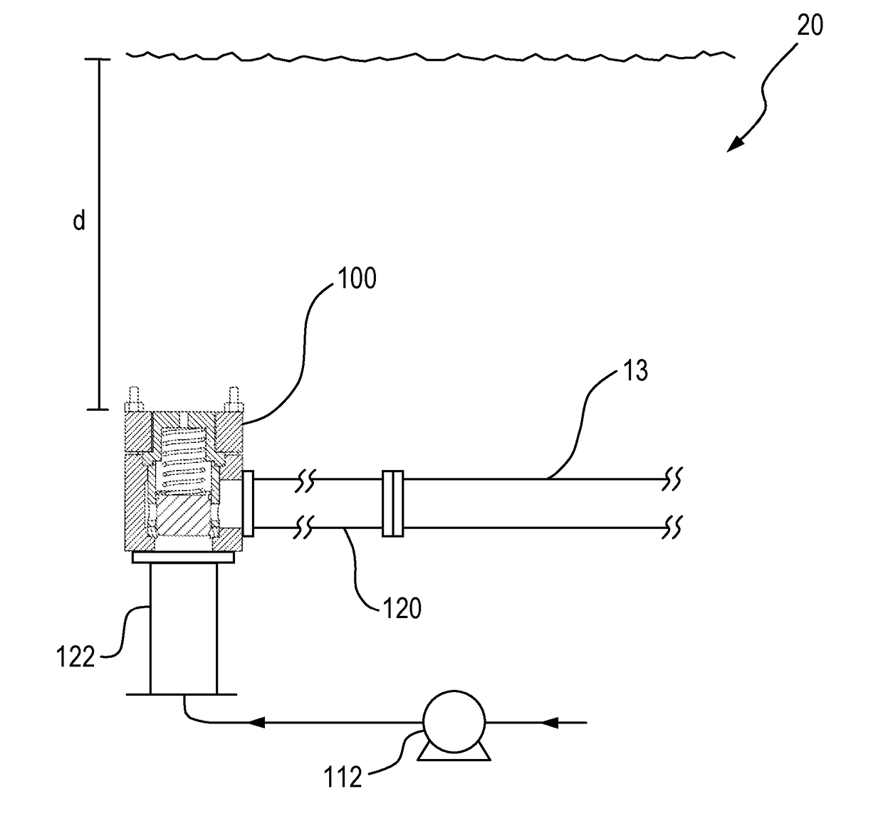
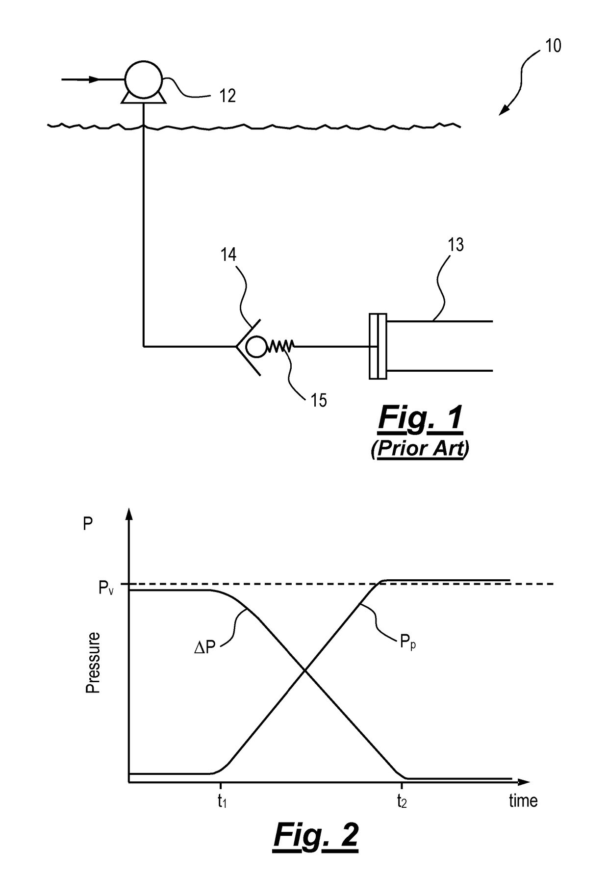
[0072]As noted above, FIG. 1 is a schematic representation of a flow system which is commonly used in the subsea industry in pipeline filling, flooding and pigging operations, and FIG. 2 is a graphical representation of pump pressure during use of the flow system in filling a pipeline. FIGS. 1 and 2 are useful for understanding the invention, an embodiment of which will now be described with reference to FIGS. 3 to 5.

[0073]The terms “upper”, “lower”, “above”, “below”, “up” and “down” may be used herein to indicate relative positions of the equipment. The invention also has applications in equipment used in orientations other than those shown in the drawings, and when these terms are applied to such orientations they may indicate “left”, “right” or other relative positions in the context of the orientation of the equipment.

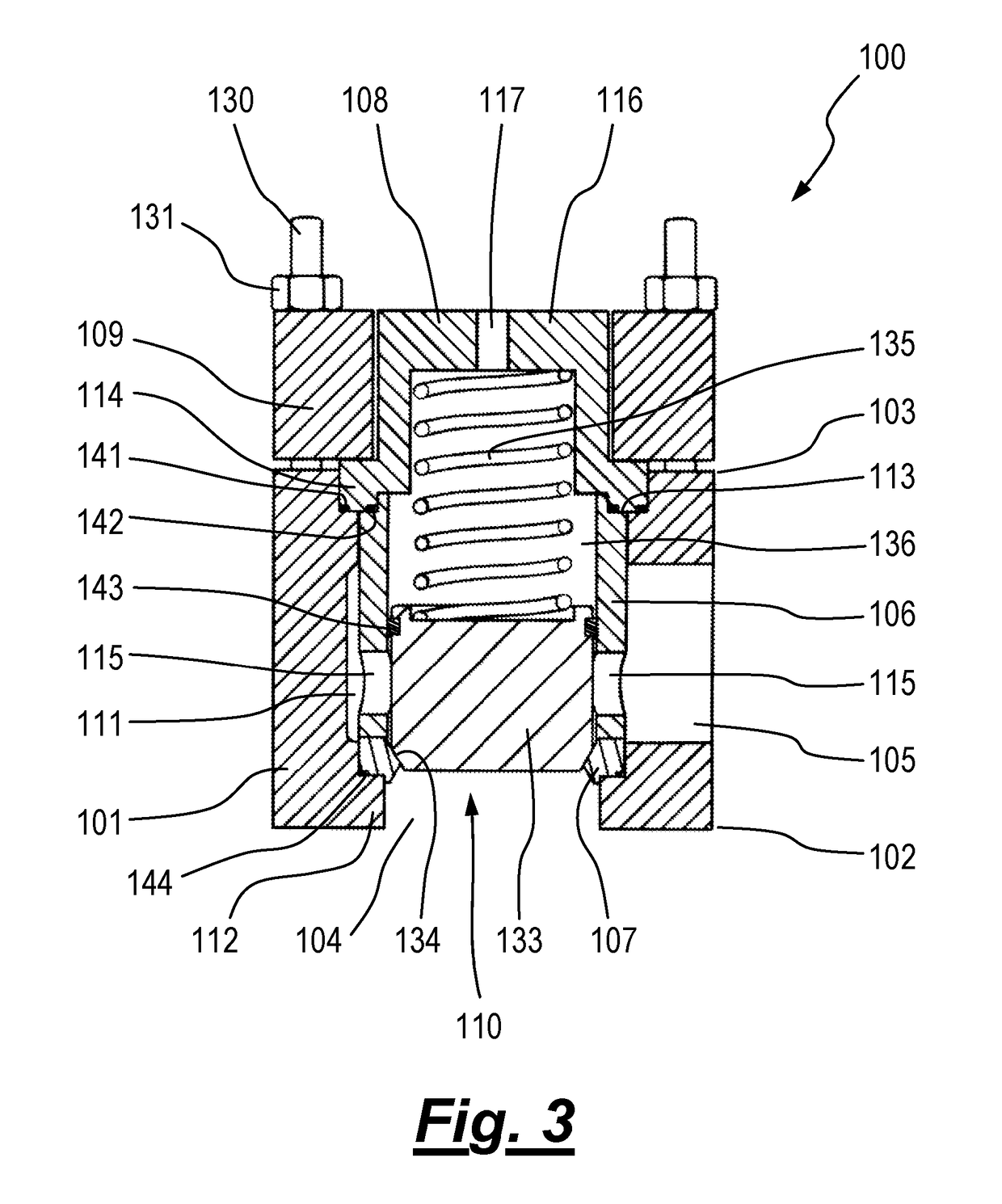
[0074]Referring firstly to FIG. 3, there is shown a subsea valve generally depicted at 100, according to a first embodiment of the invention. FIG. 4 shows the valv...


PUM


Abstract

The invention provides a flow system, a subsea valve (100), and a method of use in a subsea pipeline filling, flooding or pigging operation. The flow system comprises a subsea valve (100) comprising a valve inlet and a valve outlet configured to be coupled to a subsea pipeline (13). A pump (112) comprises a pump inlet connected to a fluid source and a pump outlet connected to the valve inlet. The pump is operable to pump fluid from the fluid source and into the subsea pipeline via the subsea valve. The subsea valve comprises a movable valve member and a biasing mechanism, by which the valve member is urged by a biasing force towards a closed position that prevents flow of fluid through the valve and into the subsea pipeline. The valve member is operable to be moved to an open position on activation of the pump to provide a pressure increase at the valve inlet sufficient to overcome the biasing force. In use, opposing sides of the valve member are exposed to ambient subsea pressure such that the subsea valve is pressure balanced.

Description

[0001]The present invention relates to a subsea valve, a flow system and a method of use, and in particular to subsea valve, a flow system and method of use in a pipeline filling, flooding or pigging application. Aspects of the invention relate to a subsea apparatus including a valve, a flow system including the subsea apparatus, and a method of use.BACKGROUND TO THE INVENTION[0002]In the field of subsea engineering, it is common to lay pipelines on the seabed in a sealed condition and full of air or gas at atmospheric pressure. After the pipeline is laid, it may be flooded with seawater and may subsequently be pressure tested to ensure that there are no fluid leaks in the pipeline.[0003]A number of subsea contractors provide systems which use combinations of hydrostatic pressure and / or a topsides or subsea booster pump for filling, flooding or pigging the pipeline, or increasing the pressure in the pipeline.[0004]In shallow water applications, it is generally preferred to use a top...

Claims


Application Information

Patent Timeline
IPC IPC(8): G01M3/00F16K15/02F16L55/46F04D13/06F04D29/22F04D15/00F04D13/08G01M3/02F16L1/12F16L101/30
CPCG01M3/005F04D13/066F04D13/08F04D15/0005F16L2101/30F16K15/026G01M3/02F16L1/12F16L55/46F04D29/22E21B41/0007E21B43/01F16K15/025E21B34/06E21B34/101E21B43/0107E21B43/013F16K31/122F16K31/1221F16L55/38
Inventor BARRON, STEPHENMARTIN, ALLAN
Owner ENERMECH
Why Eureka
Try Eureka