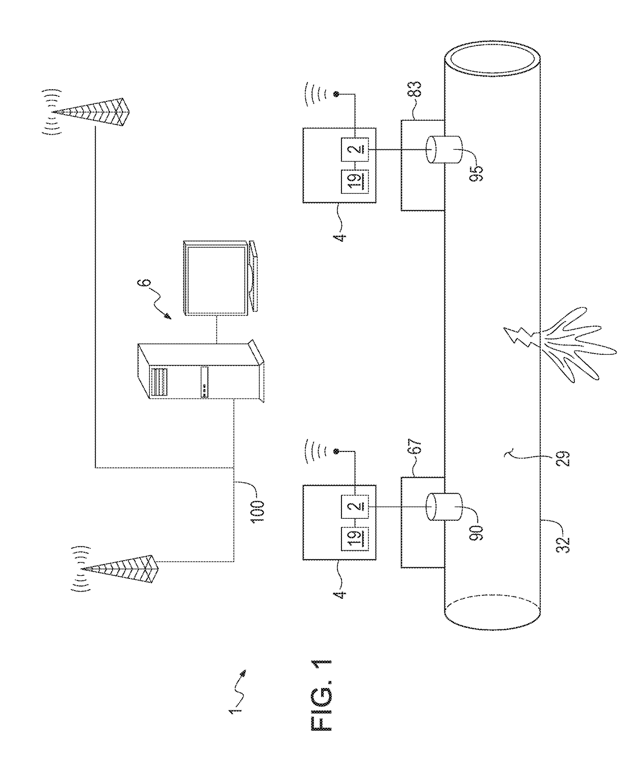
Ultrasonic Flow Meter Leak Detection System and Method

a leak detection system and ultrasonic flow technology, applied in the field of ultrasonic flow meter leak detection system and method, can solve the problems of increasing the cost of network operators, exacerbating the loss of revenue and repair cost, and significant loss of revenues

Active Publication Date: 2017-10-26
NEPTUNE TECH GROUP
View PDF3 Cites 109 Cited by
  • Summary
  • Abstract
  • Description
  • Claims
  • Application Information

AI Technical Summary

Benefits of technology

[0014]The above presents a simplified summary in order to provide a basic understanding of some aspects of the claimed subject matter. This summary is not an extensive overview. It is not intended to identify key

Problems solved by technology

Leaks in conduits carrying fluid in a distribution network, including for example water, oil, or chemicals, can result in significant lost revenues and increased cost for the operator of the network, such as a water utility.
Without a systematic method for detection and repair, le

Method used


Image

  • Ultrasonic Flow Meter Leak Detection System and Method

Examples


Embodiment Construction

[0016]Unless otherwise defined, all terms (including technical and scientific terms) used herein have the same meaning as commonly understood by one of ordinary skill in the art of this disclosure. It will be further understood that terms, such as those defined in commonly used dictionaries, should be interpreted as having a meaning that is consistent with their meaning in the context of the specification and should not be interpreted in an idealized or overly formal sense unless expressly so defined herein. Well known functions or constructions may not be described in detail for brevity or clarity.

[0017]The terms “about” and “approximately” shall generally mean an acceptable degree of error or variation for the quantity measured given the nature or precision of the measurements. Typical, exemplary degrees of error or variation are within 20 percent (%), preferably within 10%, and more preferably within 5% of a given value or range of values. Numerical quantities given in this descr...


PUM


Abstract

The use of ultrasonic transducers installed in utility meters is provided for the detection of fluid leaks in a conduit. Such transducers are normally used to transmit acoustic waves in order to measure the velocity of fluid flow, but it is disclosed that such transducers are also capable of detecting leak noises in addition to such transmitted acoustic waves.

Description

CROSS-REFERENCE TO RELATED APPLICATIONS[0001]This application site the benefit of the filing date of provisional U.S. Patent Application No. 62 / 325,825, filed on 21 Apr. 2016 (pending).FIELD OF INVENTION[0002]The invention relates generally to the field of monitoring flow including detecting leaks in a conduit, such as water in utility network.BACKGROUND[0003]Leaks in conduits carrying fluid in a distribution network, including for example water, oil, or chemicals, can result in significant lost revenues and increased cost for the operator of the network, such as a water utility. Without a systematic method for detection and repair, leaks may go undetected for a prolonged period time and become worse, thereby exacerbating the loss of revenue and cost of repair.[0004]To detect leaks, detection units and systems have been used that are temporarily clamped onto the pipe. However, such systems detect leaks only in the proximate location where they are clamped on and only for the period ...

Claims


Application Information

Patent Timeline
IPC IPC(8): G01M3/28G01F1/66
CPCG01F1/66G01M3/2807G01M3/243G01F1/666
Inventor BRENNAN, JR., WILLIAM JAMESWILSON, MICHAEL ALLENNORTHRUP, WYATT EDWARD
Owner NEPTUNE TECH GROUP
Why Eureka
Try Eureka