Display device

a display device and display technology, applied in the field of display devices, to achieve the effect of narrowing the border of the display devi

Inactive Publication Date: 2017-10-26
HANNSTAR DISPLAY CORPORATION
View PDF4 Cites 38 Cited by
  • Summary
  • Abstract
  • Description
  • Claims
  • Application Information

AI Technical Summary

Benefits of technology

[0020]Compared with prior art, the present disclosure has advantages of: the border of the display device is narrowed.

Problems solved by technology

In particular, how to meet the requirement of the narrow border for non-rectangular display devices (e.g. smart watch) is an issue concerned by people in the art.

Method used


Image

  • Display device
  • Display device
  • Display device

Examples


first embodiment

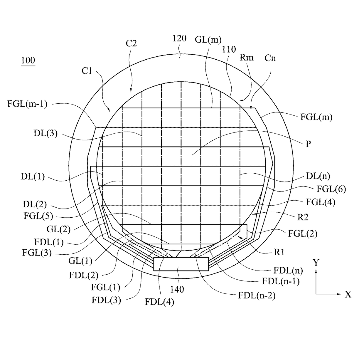
[0038]FIG. 1 is a diagram illustrating a top view of a display device according to a first embodiment. Referring to FIG. 1, a display device 100 has a display area 110 and a non-display area 120. A shape of the display area 110 is non-rectangular. In the embodiment, the display device 100 is implemented as a watch, but it may be implemented as other mobile devices, appliances, a dashboard, or any other electronic devices, and the invention is not limited thereto. In addition, the shape of the display area 110 is circular, but the shape of the non-rectangular display area may be oval, triangular, trapezoidal, heart-shaped or other irregular shapes. The shape of the non-rectangular in the disclosure is not limited to the aforementioned examples. The shape of the non-display area 120 and the shape of the display area 110 are both circular in the embodiment, but the shape of the non-display area 120 may be different from that of the display area 110 in other embodiments.

[0039]Multiple p...

second embodiment

[0055]Referring to FIG. 6, FIG. 6 is a schematic diagram illustrating a top view of a display device 200 according to the second embodiment. The difference between FIG. 6 and FIG. 1 is that multiple bonding pads 130 are disposed in the non-display area 120 in FIG. 6. The bonding pads 130 are electrically connected to the first fan-out conductive lines FGL(1)-FGL(m) and the second fan-out conductive lines FDL(1)-FDL(n). The driving circuit 140 is disposed on a flexible circuit board 150 (e.g. Tape Carrier Package (TCP) or Chip on Film (COF)), and one side of the flexible circuit board 150 has multiple first bonding leads (show shown) electrically connected to the bonding pads 130, and the other side has multiple bonding leads 160 electrically connected to a circuit board (not shown). The flexible circuit board 150 has multiple conductive wires (not shown) to electrically connect the driving circuit 140 to the first bonding leads and the second bonding leads 160, and thus the driving ...

third embodiment

[0058]Referring to FIG. 7, FIG. 7 is a schematic diagram illustrating a top view of a display device 300 according to a third embodiment. The difference between FIG. 1 and FIG. 7 is that a gate driving circuit 141 and a data driving circuit 142 are disposed in the non-display area 120 in the embodiment of FIG. 7. Rest of FIG. 7 is similar to the embodiment of FIG. 1 and will not be repeated. Multiple first fan-out conductive lines FGL(1)-FGL(m) and second fan-out conductive lines FDL(1)-FDL(n) are disposed in the non-display area 120. Each of the first fan-out conductive lines FGL(1)-FGL(m) is coupled to one of the gate lines GL(1)-GL(m) and the gate driving circuit 141. Each of the second fan-out conductive lines FDL(1)-FDL(n) is coupled to one of the data lines DL(1)-DL(n) and the data driving circuit 142. The gate driving circuit 141 and the data driving circuit 142 may be implemented as a gate driving chip and a data driving chip respectively; or one of the gate driving circuit ...


PUM


Abstract

The display device includes a display area, a non-display area, pixel structures, gate lines, data lines, first fan-out conductive lines, second fan-out conductive lines and a driving circuit. The shape of the display area is non-rectangular. The pixel structures, the gate lines and the data lines are disposed in the display area. The first fan-out conductive lines are disposed in the non-display area, and are coupled to the gate lines. The second fan-out conductive lines are disposed in the non-display area, and are coupled to the data lines. The driving circuit is coupled to the first fan-out conductive lines and the second fan-out conductive lines. The first fan-out conductive lines and the second fan-out conductive lines are formed in at least three different conductive layers.

Description

RELATED APPLICATIONS[0001]This application claims priority to China Application Serial Number 201610251643.2, filed Apr. 21, 2016, which is herein incorporated by reference.BACKGROUNDField of Invention[0002]The present invention relates to a display device. More particularly, the present invention relates to the display device having a non-rectangular display area.Description of Related Art[0003]In general, a display device has a display area and a non-display area. Pixel structures, gate lines and data lines are disposed in the display area. Fan-out conductive lines, which are coupled to the gate lines and the data lines, are disposed in the non-display area. The fan-out conductive lines are coupled to a driving chip to transmit gate signals and data signals to the gate lines and the data lines respectively. Because the fan-out conductive lines are disposed in the non-display area and are concentrated toward the driving chip, a border of the display device is required to accommodat...

Claims


Application Information

Patent Timeline
Patent Type & Authority Applications(United States)
IPC IPC(8): H01L27/12
CPCH01L27/1218H01L27/124G09G3/20G09G3/2092G02F1/1362G02F1/1345G02F2201/56H10K59/131
Inventor YEH, CHENG-YEN
Owner HANNSTAR DISPLAY CORPORATION
Why Eureka
Try Eureka