Wrench

a wrench and spanner technology, applied in the field of wrenches, can solve the problems of difficult tool fabrication, high cost, and inconvenient operation, and achieve the effects of improving the work efficiency of the wrench, simple structure, and relatively large torqu

Inactive Publication Date: 2017-11-02
HANGZHOU GREAT STAR IND CO LTD +1
View PDF9 Cites 0 Cited by
  • Summary
  • Abstract
  • Description
  • Claims
  • Application Information

AI Technical Summary

Benefits of technology

[0044](1) When the handle rotates relative to the body in a counter-clockwise direction, the jaw locking mechanism is changed to the unlocked state from the locked state, and the distance between the fixed jaw and the movable jaw is increased under the external force, thereby making the fixed jaw and the movable jaw to pass over the vertexes of the workpiece, which achieves the continuous and multiple rotation of the workpiece, without the need to remove the wrench from the workpiece or place it on the workpiece again, thereby improving the work efficiency of the wrench.
[0045](2) The wrench is simple in structure, can bear a relatively large torque, simplifies the fabrication process and lowers the fabrication cost.
[0046](3) The first elastic part is provided internally, which prevents the first elastic part from contacting greasy dirt in use while making the wrench more aesthetically pleasing.
[0047](4) The worm gear has a double thread structure, which not only shortens the time required to adjust the distance between the jaws but also increases the torque bearable by the worm gear.
[0048]The conception, specific structures and technical effects of the present invention will be further illustrated below in conjunction with the accompanying drawings, in order to fully understand the objects, features and effects of the present invention.

Problems solved by technology

Therefore, this operation is very inconvenient.
However, it is not easy to incorporate a ratchet and an adjustable function into a wrench, which leads to a relatively complex structure, difficult tool fabrication and relatively high costs.
Additionally, when a torque is relatively large, the wrench could be damaged.

Method used


Image

  • Wrench
  • Wrench
  • Wrench

Examples


Embodiment Construction

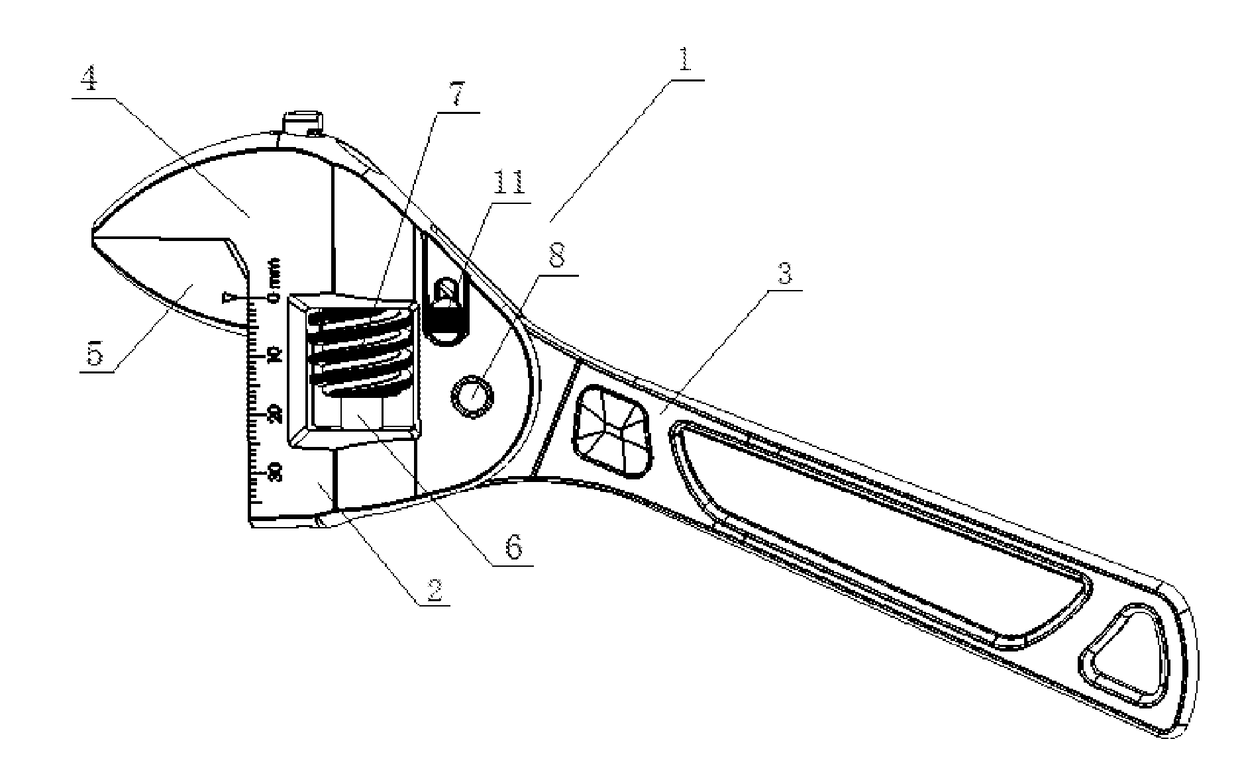
[0059]As shown in FIG. 1, the wrench 1 according to one embodiment of the present invention includes a body 2, a handle 3, a fixed jaw 4, a movable jaw 5 and an ejector pin 10.

[0060]The size of the handle 3 is designed to be suitable for holding by a user, and the handle 3 may include an injection sleeve to improve the grip comfort.

[0061]The fixed jaw 4 is fixedly connected to the body 2, or can be integrally formed with the body 2. In the present embodiment, the fixed jaw 4 is integrally formed with the body 2.

[0062]The body 2, the fixed jaw 4 and the movable jaw 5 may be made of cast steel or other high-strength materials.

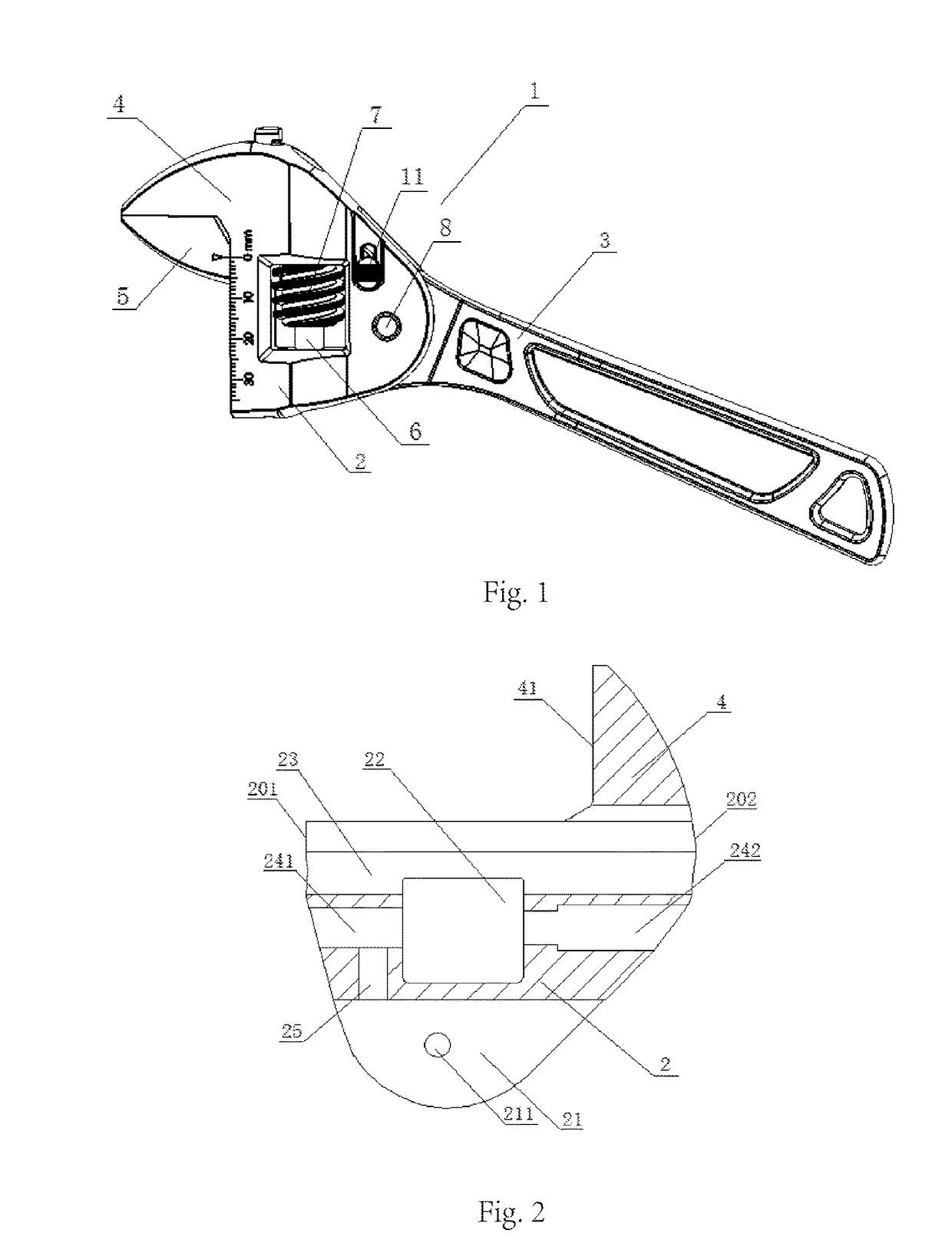
[0063]As shown in FIG. 2, the fixed jaw includes a jaw surface 41 which contacts the workpiece when the wrench is operated. Here, the workpiece may include any apparatus, part or fastener clamped by the wrench 1. The typical workpiece is a torqued fastener, such as a screw, a hexagon nut, a pip fitting or the like.

[0064]The body 2 includes an approximately rectan...


PUM


Abstract

Disclosed is a wrench, comprising a jaw locking mechanism (10) in the form of an ejector pin, being used to limit a sliding connection component (23, 241, 242) to move relative to a body (2) in a direction toward or away from a fixed jaw (4), and further comprising a handle locking mechanism which is used to limit or allow the rotation of a handle (3) relative to the body (2). By means of the wrench, continuous and multiple rotation of a workpiece is achieved.

Description

FIELD OF THE INVENTION[0001]The present invention relates to a wrench, pertaining to the field of hand tools.DESCRIPTION OF THE PRIOR ART[0002]An adjustable wrench usually comprises a fixed jaw and a movable jaw for clamping a workpiece, where the movable jaw can move toward or away from the fixed jaw. By adjusting the distance between the fixed jaw and the movable jaw, the wrench can tightly clamp a series of workpieces of various sizes, and the workpieces can be screwed or unscrewed by rotating a handle.[0003]When an ordinary adjustable wrench is used, a user adjusts the distance between the fixed jaw and the movable jaw, and places the wrench on the workpiece. In most service environments, the handle of the wrench can only rotate by a relatively small angle, thus the workpiece can be screwed or unscrewed only by continuous and multiple rotations. Between two rotations, pauses are required for temporary removals of the wrench from the workpiece, and place it on the workpiece again...

Claims


Application Information

Patent Timeline
Patent Type & Authority Applications(United States)
IPC IPC(8): B25B13/26B25B13/14
CPCB25B13/14B25B13/26
Inventor WANG, MIN
Owner HANGZHOU GREAT STAR IND CO LTD
Why Eureka
Try Eureka