Magnetical attraction socket structure

Inactive Publication Date: 2017-11-02
CHU CHIEN JU
View PDF3 Cites 2 Cited by
  • Summary
  • Abstract
  • Description
  • Claims
  • Application Information

AI Technical Summary

Benefits of technology

[0007]Thus, an object of the present invention is to provide a magnetic attraction socket structure having a broadened range of adaptation and is operable by magnetically attracting a metal flange of a spark plug so as to be adapted to spark plugs provided from different manufacturers thereby enhancing the expandability thereof.
[0008]Another object of the present invention is to provide a magnetic attraction socket structure having excellent stability, which effectively maintains the structural stability thereof to prevent undesired separation during use thereof and also to extend the service life thereof.
[0009]A further object of the present invention is to provide a magnetic attraction socket structure exhibiting excellent effect of holding for effectively holding a spark plug with extended persistency so as to easily access and remove a spark plug without a potential risk of affecting ignit

Problems solved by technology

These devices, however, have certain drawbacks in the designs thereof, often causing troubles to a user operating such devices.
For a device that uses a resilient clip to hold a spark plug, since the sizes and shapes of spark plugs provided by different manufacturers are generally inconsistent with each other.
A single clip may not satisfy different all the specifications, so that the expandability thereof is limited and the effectiveness of clamping would be poor if the specification of a spark plug to be held does not completely match.
Further, the clip that is generally made of a metal would suffer material fatigue after being used for a long while, eventually affecting the effectiveness of clamping.
The jacket is generally made of plastics and may becomes deformed or detaching due

Method used


Image

  • Magnetical attraction socket structure
  • Magnetical attraction socket structure
  • Magnetical attraction socket structure

Examples


Embodiment Construction

[0021]The following descriptions are exemplary embodiments only, and are not intended to limit the scope, applicability or configuration of the invention in any way. Rather, the following description provides a convenient illustration for implementing exemplary embodiments of the invention. Various changes to the described embodiments may be made in the function and arrangement of the elements described without departing from the scope of the invention as set forth in the appended claims.

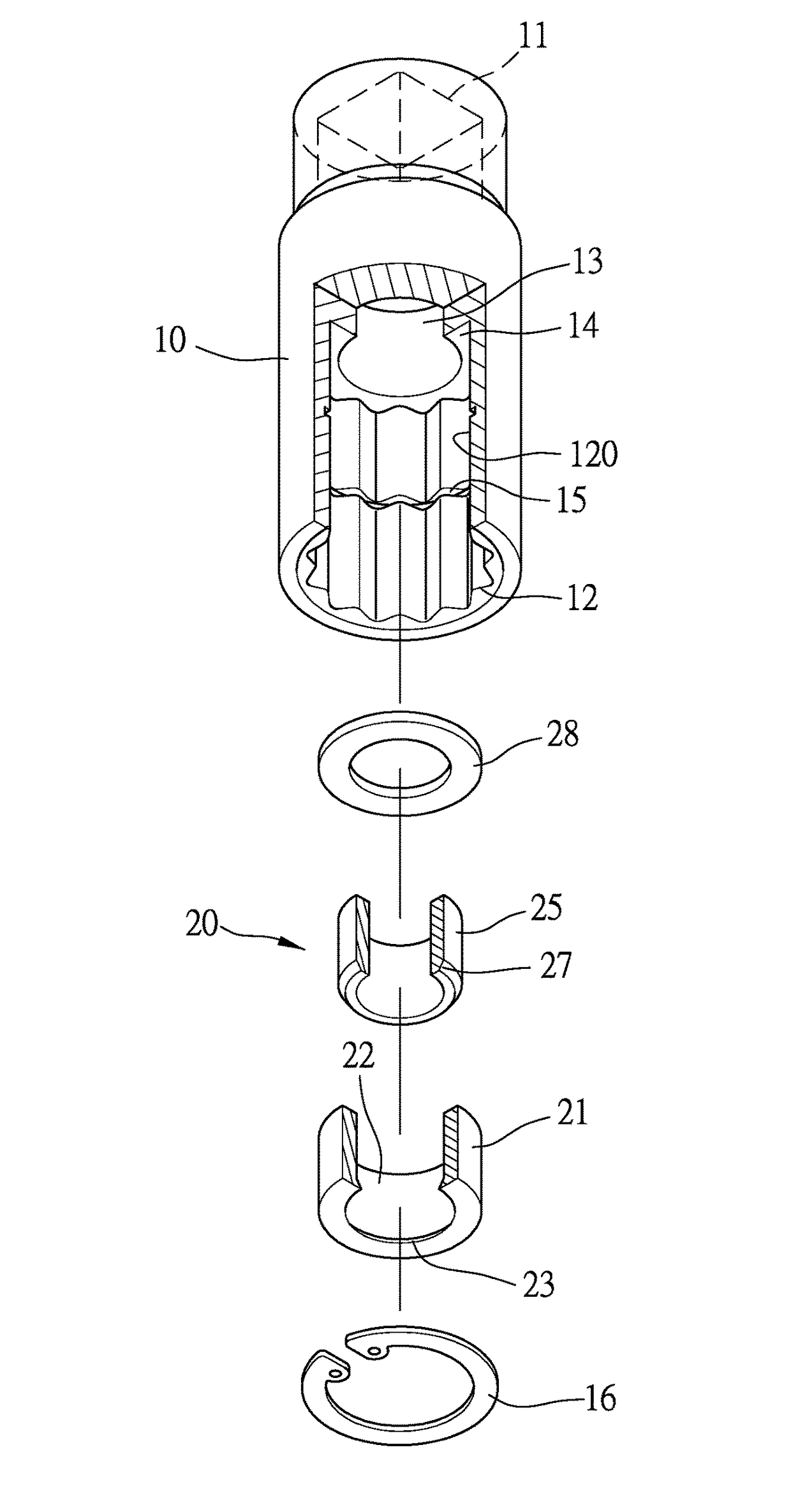
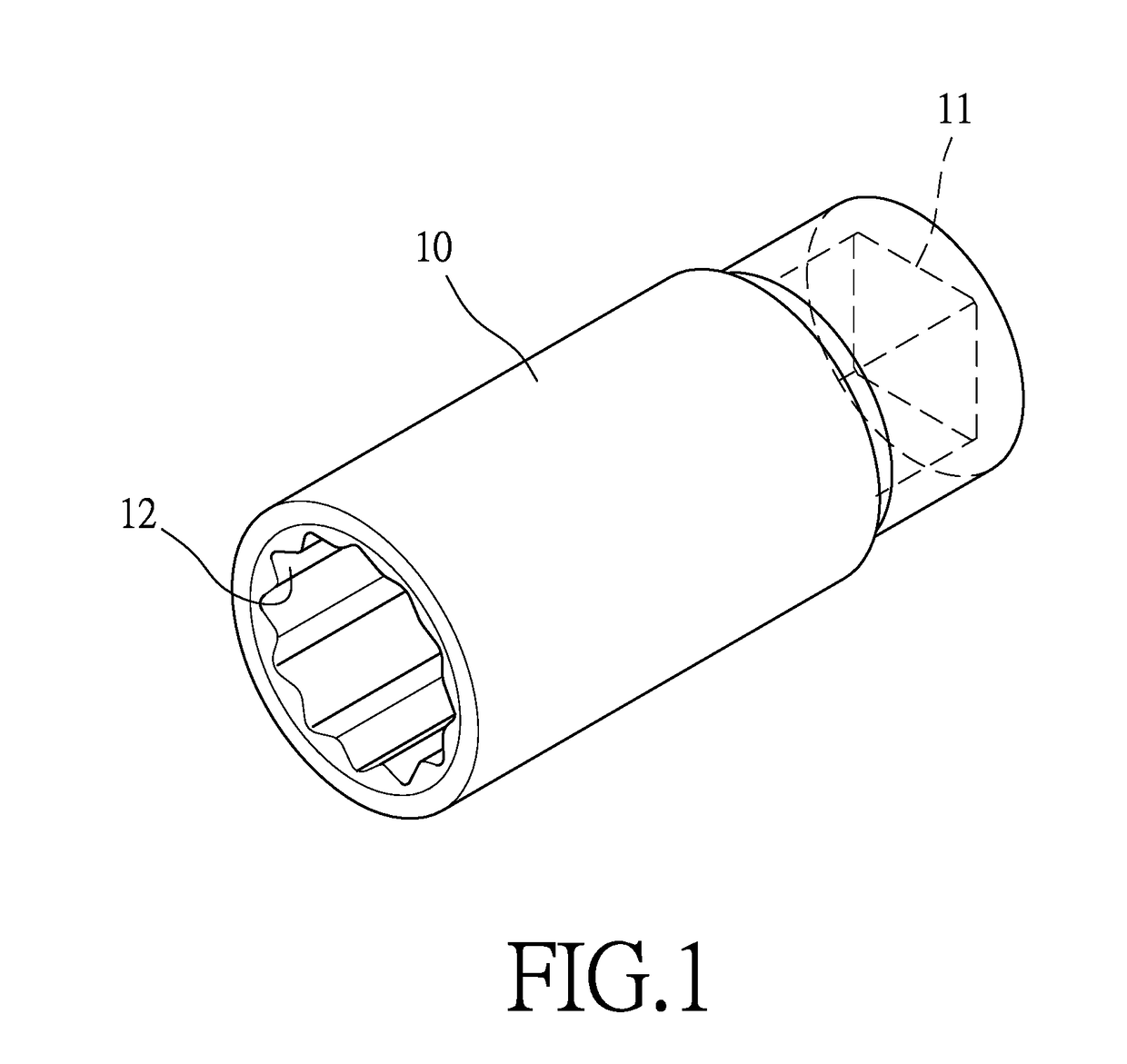
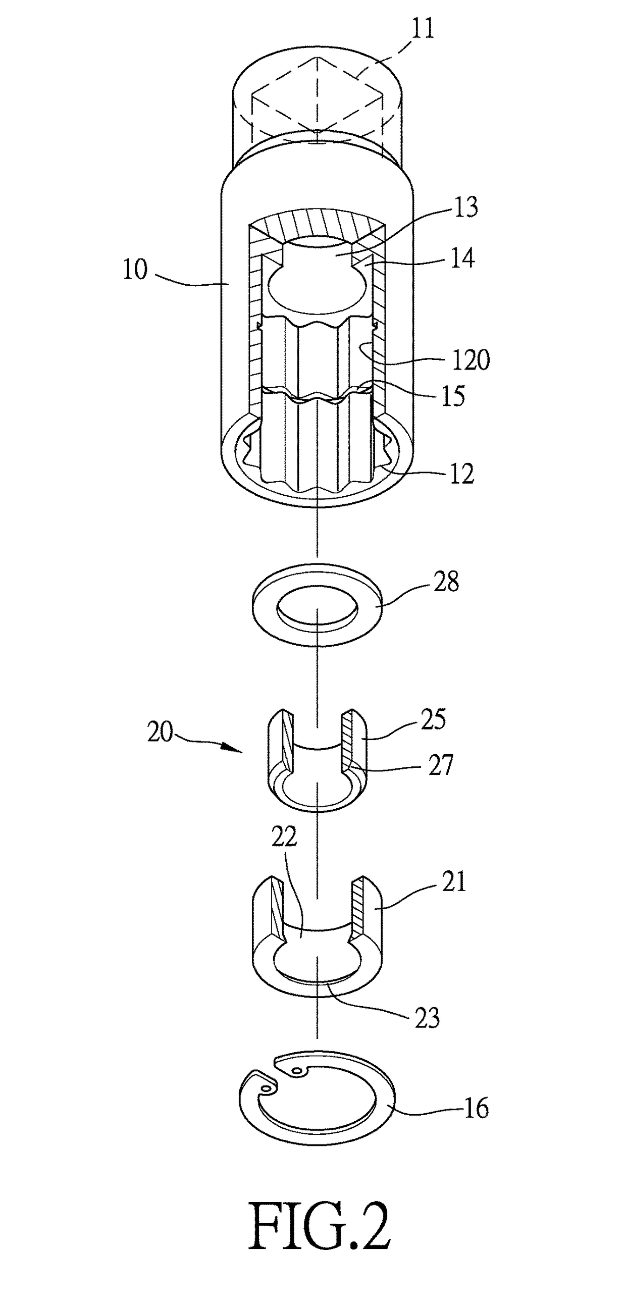
[0022]The present invention provides a magnetic attraction socket structure. As shown in FIGS. 1, 2, and 3, the magnetic attraction socket structure comprises a socket body 10 in which a magnetic attraction assembly 20 is mounted for mounting / dismounting a spark plug 50 (see FIG. 4) and allowing the spark plug 50 to be directly picked up and moved in unison therewith.

[0023]The socket body 10 has a hollow interior having two opposite ends respectively forming a driven section 11 for being selectively...


PUM


Abstract

A magnetic attraction socket structure includes a socket body and a magnetic attraction assembly mounted inside the socket body. The socket body includes an installation section formed therein at a top of which a stepped surface is formed. A circumferential groove is formed in an inner circumference of the socket body to correspond to a bottom of the installation section for receiving and holding an elastic ring clip therein. The magnetic attraction assembly has a top positioned against the stepped surface of the socket body. The magnetic attraction assembly includes an insulation jacket and an annular magnetic body, in which the insulation jacket having no permeability includes a receiving hole to receive the annular magnetic body to fit therein. The insulation jacket includes a stop on an inner circumference of the receiving hole for retaining the annular magnetic body in position.

Description

(a) TECHNICAL FIELD OF THE INVENTION[0001]The present invention relates generally to the field of mounting / dismounting technology, and more particularly to a magnetic attraction socket structure for mounting / dismounting a spark plug.(b) DESCRIPTION OF THE PRIOR ART[0002]Various sockets dedicated for spark plugs have been proposed, such as those disclosed in patent documents, U.S. Pat. No. 5,960,682, Taiwan Patent No. 372212 and 1325353, and Taiwan Utility Models M299054 and M446070, which are provided for temporarily holding a spark plug in a socket by means of attraction achieved with a magnetic member or clamping with a resilient clip in order to facilitate installation and removal of the spark plug.[0003]These devices, however, have certain drawbacks in the designs thereof, often causing troubles to a user operating such devices. Brief discussions are given below.[0004]For a device that uses a resilient clip to hold a spark plug, since the sizes and shapes of spark plugs provided...

Claims


Application Information

Patent Timeline
IPC IPC(8): B25B13/48B25B23/12B25B13/06
CPCB25B13/483B25B23/12B25B13/06
Inventor CHU, CHIEN-JU
Owner CHU CHIEN JU
Why Eureka
Try Eureka