MEMS device, liquid ejecting head, and liquid ejecting apparatus

Active Publication Date: 2017-11-02
SEIKO EPSON CORP
View PDF0 Cites 5 Cited by
  • Summary
  • Abstract
  • Description
  • Claims
  • Application Information

AI Technical Summary

Benefits of technology

[0006]An advantage of some aspects of the invention is to provide a MEMS system, a liquid ejecting head, and a liquid ejecting apparat

Problems solved by technology

There is a concern that damage such as cracks may result in the piezoel

Method used


Image

  • MEMS device, liquid ejecting head, and liquid ejecting apparatus
  • MEMS device, liquid ejecting head, and liquid ejecting apparatus
  • MEMS device, liquid ejecting head, and liquid ejecting apparatus

Examples


Embodiment Construction

[0029]Hereinafter, an aspect for realizing the invention will be described with reference to the attached drawings. In the embodiments described below, although various limitations have been made as preferred specific examples of the invention, the scope of the invention is not limited to the aspects unless specifically stated to limit the invention. In addition, in the following description, among liquid ejecting heads which are one type of MEMS device, in particular, an ink jet-type recording head (hereinafter, recording head) 3 which is a type of liquid ejecting head mounted on an ink jet-type printer (hereinafter, printer) 1, which is a type of liquid ejecting apparatus, will be described as an example.

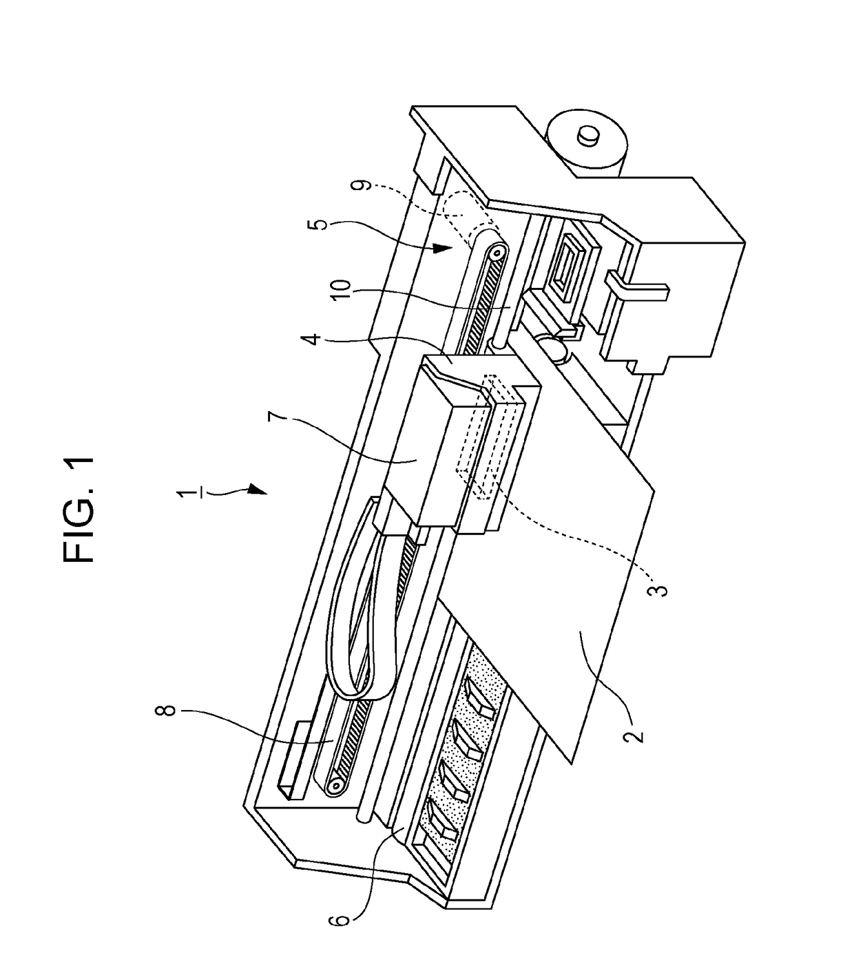
[0030]FIG. 1 is a perspective view illustrating a configuration of the printer 1. The printer 1 is an apparatus for recording an image by ejecting ink (a kind of liquid) onto a surface of a recording medium 2 (a type of printing target) such as a recording paper. The printer 1 inc...


PUM


Abstract

A MEMS device includes a first substrate in which a first electrode layer, a dielectric layer, and a second electrode layer are stacked on a driving region in this order; and a second substrate which is disposed to face a surface on which the dielectric layer of the first substrate is stacked. The first electrode layer and the dielectric layer extend beyond the second electrode layer toward a non-driving region separated from the driving region, a first resin having elasticity is disposed in a region including an end of the second electrode layer in an extending direction of the dielectric layer, and the first substrate and the second substrate are fixed with an adhesive in a state where the elastically deformed first resin is sandwiched therebetween.

Description

[0001]The entire disclosure of Japanese Patent Application No: 2016-088878, filed Apr. 27, 2016 is expressly incorporated by reference herein in its entirety.BACKGROUND1. Technical Field[0002]The present invention relates to a MEMS device which is used for ejection or the like of a liquid, a liquid ejecting head, and a liquid ejecting apparatus, and more particularly to a MEMS device in which a first electrode layer, a dielectric layer, and a second electrode layer are sequentially stacked on a driving region, a liquid ejecting head, and a liquid ejecting apparatus.2. Related Art[0003]A micro electro mechanical systems (MEMS) device is applied to various devices. For example, a liquid ejecting head, which is a type of MEMS device, is applied to a liquid ejecting apparatus used for various types of manufacturing as opposed to a liquid ejecting apparatus used for image recording an ink jet-type printer, an ink jet-type plotter, or the like. Specifically, the liquid ejecting head is ap...

Claims


Application Information

Patent Timeline
IPC IPC(8): B41J2/14
CPCB41J2/14209B41J2/04B41J2/14233B41J2/161B41J2/1623B41J2/1626B41J2/1631B41J2/1642B41J2/1646B41J2002/14491
Inventor SAIMEN, MUNEHIDEHIRAI, EIJUNAKAYAMA, MASAO
Owner SEIKO EPSON CORP
Why Eureka
Try Eureka