
Engine mount for vehicle

Active Publication Date: 2017-11-02
HYUNDAI MOTOR CO LTD
View PDF2 Cites 16 Cited by
  • Summary
  • Abstract
  • Description
  • Claims
  • Application Information

AI Technical Summary

Benefits of technology

The present invention provides a semi-active engine mount for a vehicle that improves NVH performance and ride quality by decreasing dynamic characteristics when the vehicle idles and increasing a loss factor during the driving operation of the vehicle. This results in improved driving vibration and idling vibration performance, while minimizing costs and weights through a reduction in the number of components and simplified structure. The engine mount is also advantageous in terms of packaging and compatibility with existing hydraulic mounts in vehicles.

Problems solved by technology

Usually, the engine mount formed from a rubber material has a drawback of being vulnerable to low-frequency and large-displacement vibration.
Accordingly, the engine mount cannot sufficiently satisfy both high-frequency and low-amplitude vibration and low-frequency and large-displacement vibration.
However, due to of the nature of the current hydraulic mount, a loss factor tends to decrease when dynamic characteristics decrease and the dynamic characteristics tend to increase when the loss factor increases.
In particular, the semi-active mount decreases dynamic characteristics when the vehicle idles and increases a loss factor during the driving operation of the vehicle.
However, when the current semi-active mount, a coil having high capacity that corresponds to rigidity of a rubber spring needs to be applied, costs and weights are greatly increased due to a number of components being required and a structure thereof is being complex.
The current semi-active mount is disadvantageous in terms of packaging due to a size greater than that of the existing hydraulic mount.

Method used


Image

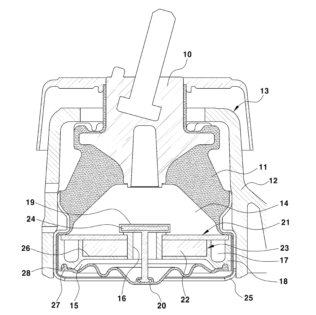
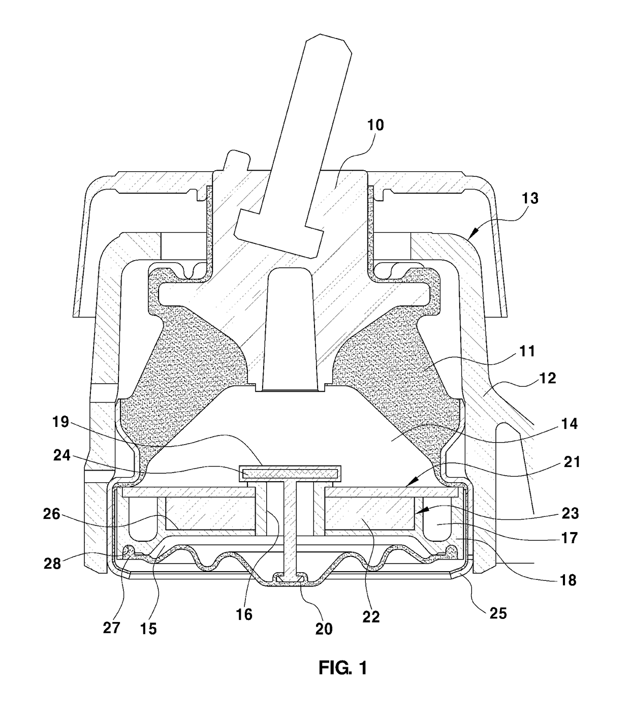
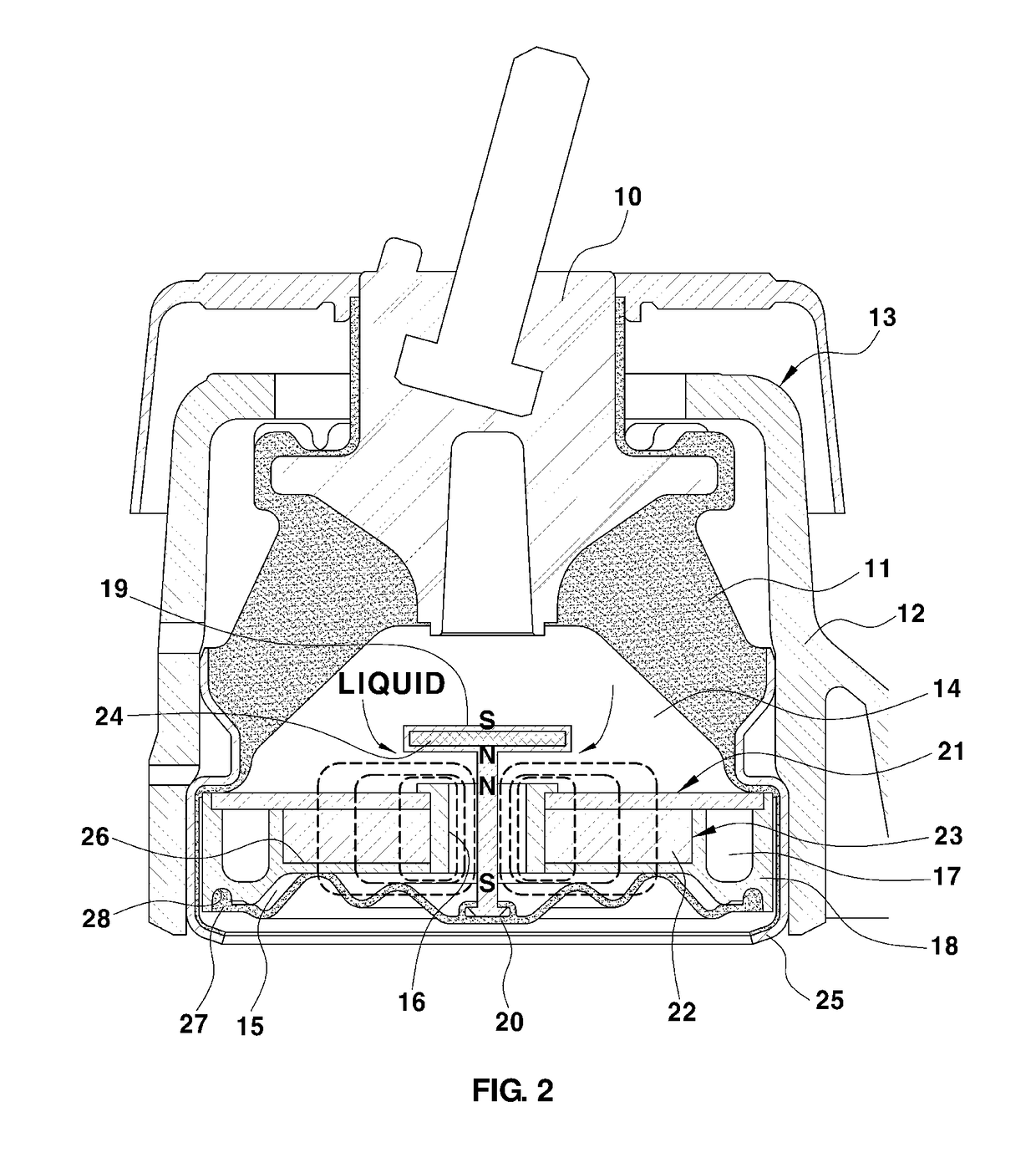
  • Engine mount for vehicle
  • Engine mount for vehicle
  • Engine mount for vehicle

Examples


Embodiment Construction

[0044]Hereinafter reference will now be made in detail to various exemplary embodiments of the present invention, examples of which are illustrated in the accompanying drawings and described below. While the invention will be described in conjunction with exemplary embodiments, it will be understood that present description is not intended to limit the invention to those exemplary embodiments. On the contrary, the invention is intended to cover not only the exemplary embodiments, but also various alternatives, modifications, equivalents and other exemplary embodiments, which may be included within the spirit and scope of the invention as defined by the appended claims.

[0045]The terminology used herein is for the purpose of describing particular embodiments only and is not intended to be limiting of the invention. As used herein, the singular forms “a”, “an” and “the” are intended to include the plural forms as well, unless the context clearly indicates otherwise. It will be further ...


PUM


Abstract

A semi-active engine mount for a vehicle is provided to improve the NVH performance and ride quality. An engine mount for a vehicle includes a rubber module with a rubber having a core therein, and a case that surrounds an exterior circumference of the rubber and a fluid module with a module case coupled to the rubber module to define an upper and lower chamber and having straight and a bypass flow paths, a closure configured to open or close the straight flow path, and a diaphragm installed on the module case to close the lower chamber. A coil module has a coil embedded in the fluid module and configured to open and close the closure when a power source is turned on or off. In particular, a high loss factor when the vehicle travels is reduced, and decreasing dynamic characteristics when the vehicle idles is decreased.

Description

CROSS-REFERENCE TO RELATED APPLICATION[0001]This application claims under 35 U.S.C. §119(a) the benefit of Korean Patent Application No. 10-2016-0052681 filed on Apr. 29, 2016, the entire contents of which are incorporated herein by reference.BACKGROUND(a) Technical Field[0002]The present disclosure relates to an engine mount for a vehicle and more particularly, to a semi-active engine mount for a vehicle capable of improving noise, vibration, and harshness (NVH) performance and ride quality by decreasing dynamic characteristics of the mount when the vehicle idles and increasing a loss factor during the driving operation of the vehicle.(b) Background Art[0003]Generally, an engine mount prevents vibration of an engine from being transmitted to a vehicle body, insulates a vibration mode of a vehicle and control motion of the engine. The engine mount minimizes motion of the engine by making the engine mount hard statically and insulates the high-frequency vibration by making the engine...

Claims


Application Information

Patent Timeline
IPC IPC(8): B60K5/12F16F13/08F16F13/26
CPCB60K5/1283F16F13/26F16F13/08B60K5/1208F16F13/262B60K5/12F16F13/1463F16F13/28
Inventor YOON, HYOUNG JIN
Owner HYUNDAI MOTOR CO LTD
Learn More