Moment resisting bi-axial beam-to-column joint connection

a moment-resisting connection and beam-to-column technology, applied in the direction of manufacturing tools, metal working equipment, welding/soldering/cutting articles, etc., can solve the problems of large vertical plane rotational demands of beam-to-column moment-resisting connections in steel frame buildings, rely on technically uncertain and costly means to transfer significant moment forces, and the method is self-limiting

Inactive Publication Date: 2017-11-02
MITEK HLDG INC
View PDF5 Cites 57 Cited by
  • Summary
  • Abstract
  • Description
  • Claims
  • Application Information

AI Technical Summary

Benefits of technology

[0010]In still another aspect, a method of assembling a prefabricated column assembly generally comprises providing a hollow tubular column. A gusset plate assembly including a plurality of gusset plates is assembled by attaching at least two of the gusset plates together. The gusset plate assembly is secured to the hollow tubular column to form the column assembly. A first pair of the gusset plates extends laterally outward from the column along a first axis and defines a space for receiving an end portion of a first beam for mounting the first beam on the first pair of gusset plates. A second pair of the gusset plates extends laterally outward from the column along a second axis. The second pair of gusset plates defines a space for receiving an end portion of a second beam for mounting the second beam on the second pair of gusset plates thereby providing for bi-axial joint connection.

Problems solved by technology

That is, the beam-to-column moment-resisting connections in a steel frame building can be subjected to large rotational demands in the vertical plane due to interstory lateral building drift.
Conventional methods of connecting an HHS column to a wide flange beam must rely on technically uncertain and costly means to transfer significant moment forces to the webs of HSS columns.
This method is self-limiting when the applied moment approaches the full flexural strength of the beam because of the inherent flexibility of the thin wall thickness of the HSS flange.
Therefore, the direct welding technique has limited capacity to transfer applied moment forces through out-of-plane bending and shear to the connecting webs of the HSS column.
These type of connections have proven to be both costly to fabricate and uncertain in their performance when subjected to violent earthquakes.
For example, the connection may be inherently susceptible to out-of-plane punching shear failures in the through-plate due to cyclic tensile forces in the column.
This connection is inherently difficult to fabricate and erect.
The fabrication of this connection type is difficult because of precise fit up issues and access for welding of interior diaphragm plates to inside faces of the HSS column.

Method used


Image

  • Moment resisting bi-axial beam-to-column joint connection
  • Moment resisting bi-axial beam-to-column joint connection
  • Moment resisting bi-axial beam-to-column joint connection

Examples


Embodiment Construction

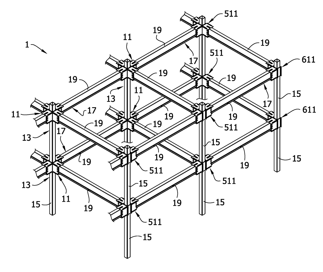
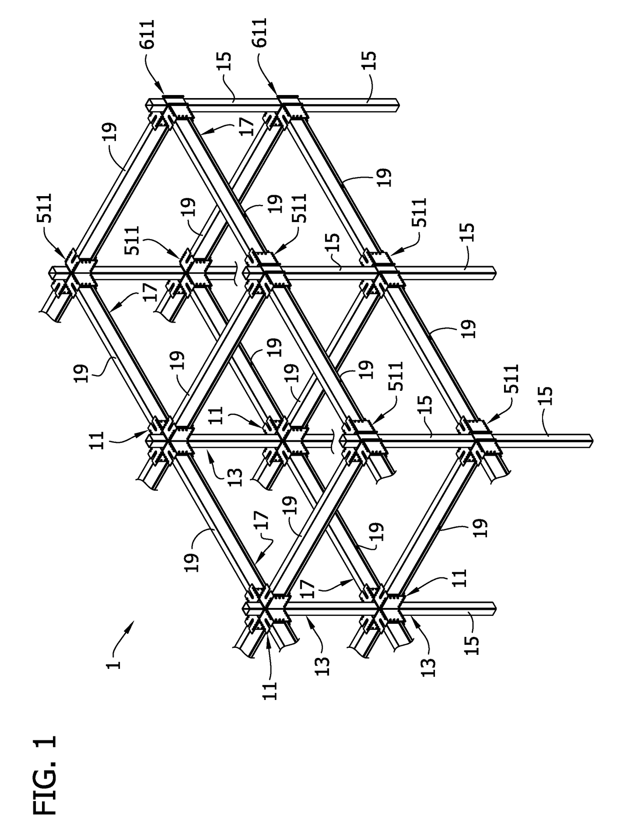
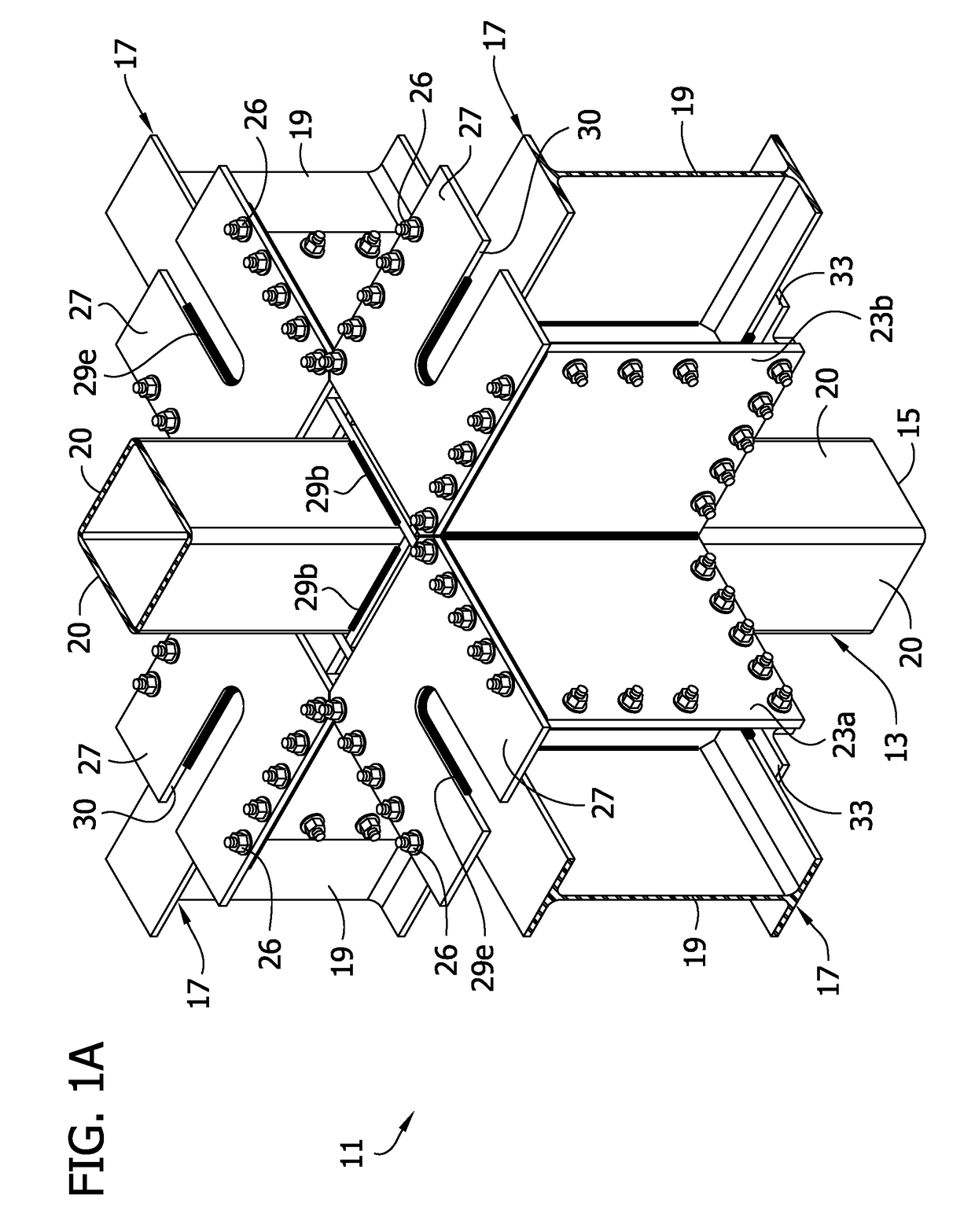
[0084]Referring to FIGS. 1-15, a bi-axial beam-to-column moment-resisting joint connection structure including a column assembly of a first embodiment is generally indicated at 11. The joint connection structure may be used in the construction of a building framework 1 (see, FIG. 1). In the illustrated embodiment, the joint connection structure joins a column assembly 13 including a column 15 to a plurality of full-length beam assemblies 17 each including a full-length beam 19. A full-length beam is a beam that has a length sufficient to extend substantially the full-length between adjacent columns in a structure (see, FIG. 2). Thus, a stub and link beam assembly as shown in FIGS. 5 and 16 of U.S. Pat. No. 6,138,427, herein incorporated by reference, is not a full-length beam. It will be understood that the beams 19 in FIG. 1A have been broken away, but are full-length beams. In the illustrated embodiment, the joint connection structure has a 4-sided / 4-beam configuration whereby fou...


PUM

PropertyMeasurementUnit
weightaaaaaaaaaa
energyaaaaaaaaaa
strengthaaaaaaaaaa

Abstract

A prefabricated column assembly includes a hollow tubular column having a longitudinal axis. A gusset plate assembly includes a plurality of gusset plates connected to the column and extending laterally outward from the column in planes generally parallel to the longitudinal axis of the column. A first pair of the gusset plates extends laterally outward from the column along a first axis and defines a space for receiving an end portion of a first beam for mounting the first beam on the first pair of gusset plates. A second pair of the gusset plates extends laterally outward from the column along a second axis that is nonparallel and non-coincident with the first axis. The second pair of gusset plates defines a space for receiving an end portion of a second beam for mounting the second beam on the second pair of gusset plates to provide a bi-axial joint connection.

Description

FIELD OF THE INVENTION[0001]The present invention generally relates to a moment resisting, bi-axial beam-to-column joint connection, and more particular to a column assembly and gusset plate assembly for a bi-axial beam-to-column joint connection.BACKGROUND OF THE INVENTION[0002]It has been found in a moment-resisting building having a structural steel framework, that most of the energy of an earthquake, or other extreme loading condition, is absorbed and dissipated, in or near the beam-to-column joints of the building.[0003]It is desirable to achieve greater strength, ductility and joint rotational capacity in beam-to-column connections in order to make buildings less vulnerable to disastrous events. Greater connection strength, ductility and joint rotational capacity are particularly desirable in resisting sizeable moments in both the lateral and the vertical plane. That is, the beam-to-column moment-resisting connections in a steel frame building can be subjected to large rotatio...

Claims


Application Information

Patent Timeline
Patent Type & Authority Applications(United States)
IPC IPC(8): E04B1/19E04B1/30E04B1/24B23K101/28
CPCE04B1/1912E04B1/2403E04B1/30E04B2001/1993B23K2201/28E04B2001/2418E04B2001/2415E04B2001/1957E04B2001/2406E04B2001/2454E04B2001/2478B23K2101/28
Inventor HOUGHTON, DAVID L.HUYNH, QUANG MINHRAFEZY, BEHZADADAMS, JARED J
Owner MITEK HLDG INC
Why Eureka
Try Eureka