Hollow blade body, insertion rib, and hollow blade

a hollow blade and body technology, applied in the field of hollow blades, can solve the problems of reducing the service life of the blade, deformation of the blade, and high temperature of the blade, and achieve the effects of preventing buckling of the leading edge, small production tolerance, and strong stiffening of the hollow blad

Inactive Publication Date: 2017-11-02
SIEMENS AG
View PDF0 Cites 1 Cited by
  • Summary
  • Abstract
  • Description
  • Claims
  • Application Information

AI Technical Summary

Benefits of technology

[0012]It is advantageous that at least one of the blade connection elements has at least one blade wall groove introduced into the blade wall. At least one of the blade connection elements advantageously has at least one blade projection projecting from the blade wall. The blade wall groove and the blade projection make it possible for the insertion rib to be introduced into the hollow blade body for example simply by pushing.
[0013]It is advantageous that the first and second blade connection elements each have a blade projection which projects from the blade wall and, with the blade wall, bounds a groove, wherein one of the two grooves is open toward the leading edge of the hollow blade body, and the other of the two grooves is open toward the trailing edge of the hollow blade body, such that a rotational movement of the insertion rib allows the rib connection elements to be brought into engagement with the blade connection elements. The insertion rib advantageously has an axis of rotation and the first and second rib connection elements advantageously each have a rib projection, wherein, when the insertion rib is rotated about the axis of rotation in a direction of rotation, the rib projections project from the insertion rib in their direction of rotation, such that the rotation allows the rib projections to be brought into locking engagement with grooves of the blade connection elements. The rotation then allows the insertion rib itself to be brought into engagement with the hollow blade body, if the separation between the pressure side and the suction side varies along the blade height, as a result of which the insertion rib cannot be pushed.
[0014]The hollow blade body advantageously has a blade rib extending from the pressure side to the suction side such that, within the hollow blade body, there are formed a leading-edge channel in the region of the leading edge of the hollow blade body and a trailing-edge channel in the region of the trailing edge, wherein the blade connection elements are arranged in the leading-edge channel. During operation of the turbomachine, the leading edge of the hollow blade can buckle. Providing the insertion rib in the leading-edge channel stiffens the leading edge and thus advantageously prevents buckling of the leading edge.
[0015]It is advantageous that the insertion rib has at least two transverse webs which are securely connected to one another and are arranged next to one another in the direction from the leading edge to the trailing edge of the hollow blade, wherein at least one of the rib connection elements is arranged at each longitudinal end of the transverse webs. By virtue of the fact that the at least two transverse webs are each provided with two rib connection elements, the preferred insertion rib has at least four rib connection elements which are in locking engagement with at least four corresponding blade connection elements. This makes it possible to bring about particularly strong stiffening of the hollow blade.
[0016]The insertion rib is advantageously produced by a casting process, by bending a sheet material, by selective laser sintering and / or selective laser melting. In the case of selective laser sintering and selective laser melting, it is advantageously possible to obtain small production tolerances and a complex geometry. Bending of a sheet material is advantageously a simple production process.
[0017]It is advantageous that the blade connection elements in engagement with the rib connection elements form an angle connection, a dovetail connection, a toothed connection and / or an omega connection. These connections are advantageously hook-like, solid connections which do not come loose during operation of the turbomachine. The hollow blade advantageously has a baffle plate which has a plurality of holes and is arranged within the hollow blade such that, via the holes, a cooling fluid can be made to flow against the surface of the insertion rib. It is thus possible to use impingement cooling to cool a large surface area of the hollow blade.

Problems solved by technology

In particular in the turbine section of a gas turbine, the blades are exposed to a high temperature, which can reduce the service life of the blades.
For example, the high temperature can cause deformation of the blades.
If the wall thickness of the blades is too great, this disadvantageously leads to a high temperature of the blades.
If, however, the wall thickness is too small, this disadvantageously leads to inadequate strength of the blades.

Method used


Image

  • Hollow blade body, insertion rib, and hollow blade
  • Hollow blade body, insertion rib, and hollow blade
  • Hollow blade body, insertion rib, and hollow blade

Examples


Embodiment Construction

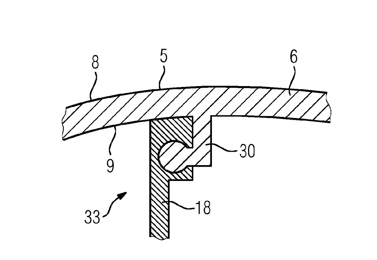
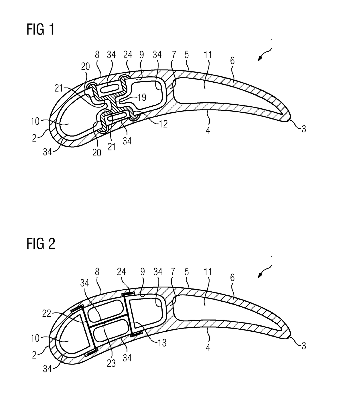
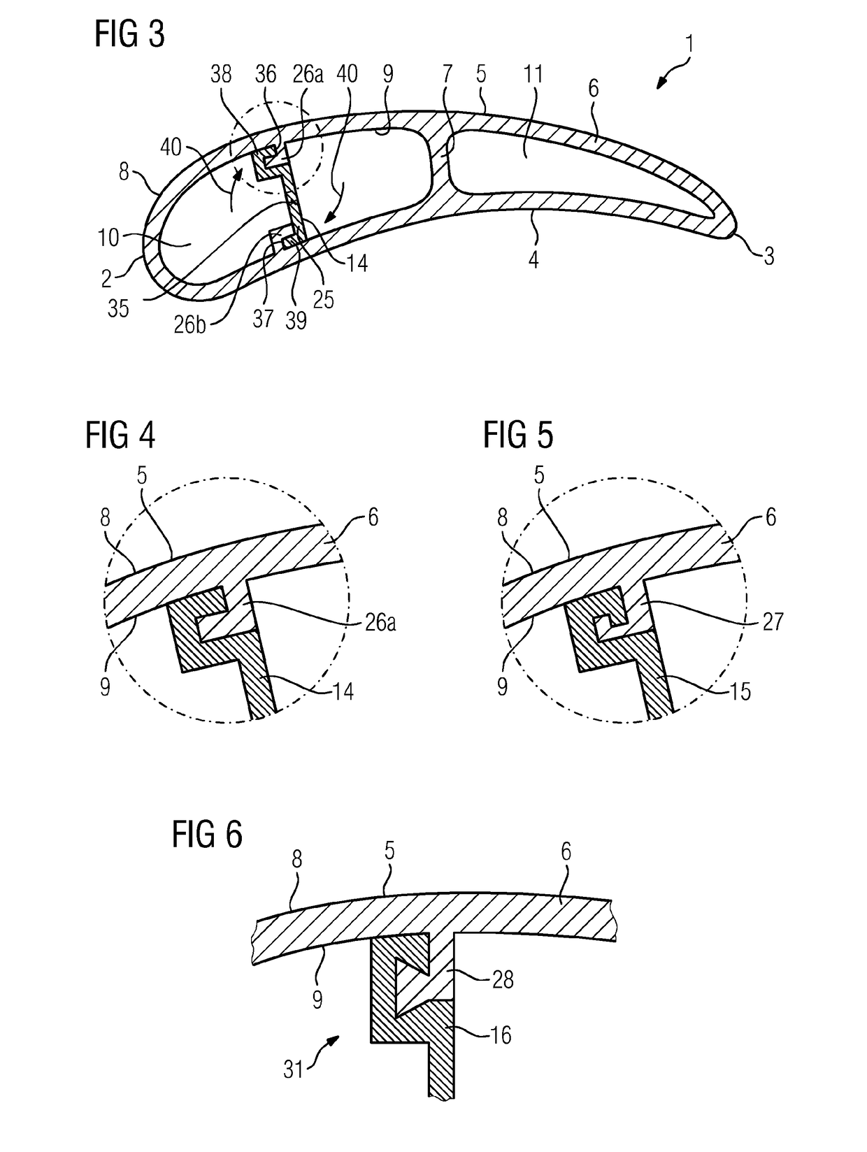
[0027]As shown in FIGS. 1 to 3, a hollow blade 1 has a hollow blade body and an insertion rib. The hollow blade body has a blade wall 6 with an outer side 8 and an inner side 9. The inner side 9 bounds an internal cavity of the hollow blade body. During operation of a turbomachine in which the hollow blade 1 is installed, the outer side 8 is exposed to a flow of a working fluid of the turbomachine. The hollow blade body also has a leading edge 2 pointing in the upstream direction of the working fluid, and a trailing edge 3 pointing in the downstream direction of the working fluid. The hollow blade body also has a pressure side 4 and a suction side 5.

[0028]The hollow blade body has a blade rib 7 which extends from the pressure side 4 to the suction side 5, such that the cavity of the hollow blade 1 is divided into a leading-edge channel 10 arranged in the region of the leading edge 2, and a trailing-edge channel 11 arranged in the region of the trailing edge 3.

[0029]The hollow blade ...


PUM


Abstract

A hollow blade body for a hollow blade, has a blade wall which has a pressure side which has at least one first blade connection element on the inner side thereof, and a suction side which has at least one second blade connection element diametrically opposite to the first blade connection element on the inner side thereof, wherein the first blade connection element can be engaged with at least one first rib connection element which is arranged on a first longitudinal end of an insertion rib, and the second blade connection element can be engaged with at least one second rib connection element which is arranged on a second longitudinal end of the insertion rib facing away from the first longitudinal end in such a way that the insertion rib is fixed on the hollow blade body and effects a stiffening of the hollow blade.

Description

CROSS REFERENCE TO RELATED APPLICATIONS[0001]This application is the US National Stage of International Application No. PCT / EP2015 / 074153 filed Oct. 19, 2015, and claims the benefit thereof. The International Application claims the benefit of European Application No. EP14194337 filed Nov. 21, 2014. All of the applications are incorporated by reference herein in their entirety.FIELD OF INVENTION[0002]The invention relates to a hollow blade for a turbomachine.BACKGROUND OF INVENTION[0003]A turbomachine has a flow duct which is bounded radially inwardly by a shaft and radially outwardly by a casing. The turbomachine has rotor blades which are secured to the shaft and rotate with the shaft during operation of the turbomachine, and stator blades which are secured to the casing and are stationary. In particular in the turbine section of a gas turbine, the blades are exposed to a high temperature, which can reduce the service life of the blades. For example, the high temperature can cause ...

Claims


Application Information

Patent Timeline
Patent Type & Authority Applications(United States)
IPC IPC(8): F01D5/18F01D5/14
CPCF01D5/188F01D5/147F05D2260/20F05D2260/30F05D2220/32
Inventor AHMAD, FATHIBUCHHOLZ, BJORNGOSSILIN, RALPHKOCH, DANIELAMATTHEIS, THORSTENRADULOVIC, RADANSCHULER, MARCO
Owner SIEMENS AG
Why Eureka
Try Eureka