

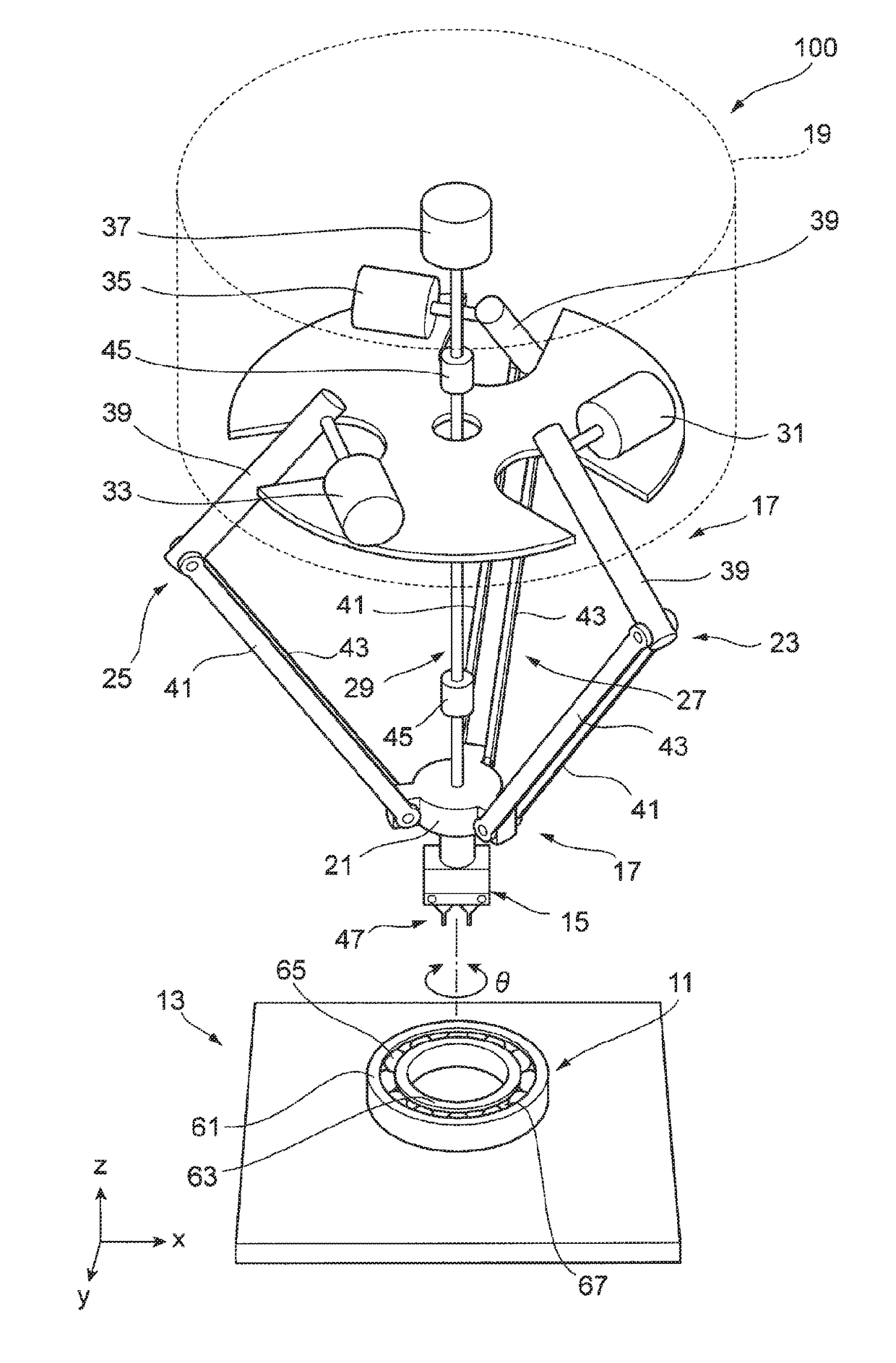
Ball arranging method and device for ball bearing, and ball bearing manufactured by said ball arranging method
a technology of ball arranging and ball arranging, which is applied in the direction of programmed manipulators, manufacturing tools, mechanical instruments, etc., can solve the problems of difficult to manufacture ball arrows, difficult to accurately distribute balls at equally spaced intervals, and high cost, so as to prevent ball damage and ball arranging errors, and perform the set change in a short time. , the effect of reducing the takt tim
- Summary
- Abstract
- Description
- Claims
- Application Information
AI Technical Summary
Benefits of technology
Problems solved by technology
Method used
Image

Examples
first modified embodiment
[0113]Subsequently, the ball gathering sequence and the ball distribution sequence is described.
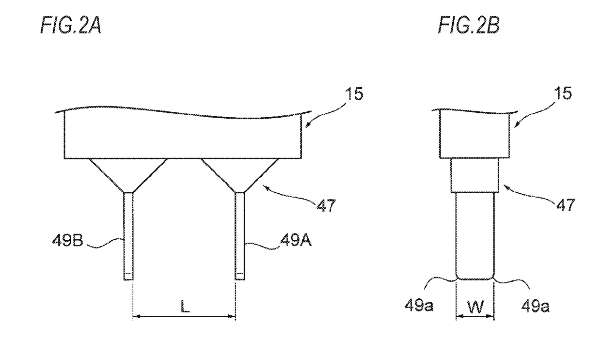
[0114]It is presumed that when implementing the ball gathering, no ball exists at the position (the area Wa) at which the pair of plate members 49A. 49B of the claw-shaped jig 47 is to be inserted into the gap space. However, in this sequence, the ball bearing is captured by an imaging unit, and when it is confirmed that there is a ball in the area Wa of the gap space, the insertion position of the pair of plate members 49A. 49B of the claw-shaped jig 47 is changed. Otherwise, the insertion position is not changed.
[0115]FIG. 10 is an enlarged perspective view of the claw-shaped jig 47, showing a manner where the claw-shaped jig 47 of the robot arm tip is provided with an imaging unit. To a part of the claw-shaped jig 47, an imaging unit 71 including an imaging element, of which an imaging area is set towards the extension direction of the plate members 49A, 49B, and a lens is attached.
[01...
second modified embodiment
[0121]Subsequently, the ball gathering sequence and the ball distribution sequence is described.
[0122]The above-described ball gathering sequence and the ball distribution sequence are implemented for the single-row ball bearing but can also be implemented for a double-row ball bearing. In the ball gathering sequence and the ball distribution sequence, the ball gathering and the ball distribution are performed for the balls of the double-row ball bearing by the claw-shaped jig, in the same manner as the above-described manner.
[0123]FIG. 13 is a sectional view of a double-row ball bearing. A double-row ball bearing 75 includes a first ball row 77 and a second ball row 79, and the plurality of balls 65 are inserted in each ball row. In this case, as shown in FIG. 14, the plate members 49A, 49B of the claw-shaped jig 47 has a length at least larger than an axial length (an extension height H) between ball center positions of the ball 65 of the first ball row 77 and the ball 65 of the s...
PUM
| Property | Measurement | Unit |
|---|---|---|
| angle | aaaaa | aaaaa |
| time | aaaaa | aaaaa |
| diameter | aaaaa | aaaaa |
Abstract
Description
Claims
Application Information