Intergrated barrier for protecting the coil of air core reactor from projectile attack

a technology for air core reactors and intergrated barriers, which is applied in the direction of transformers/inductance details, fixed inductances without magnetic cores, electric devices, etc., can solve the problems of cascading failures and the current struggle of the industry to assess and develop physical security strategies, and achieve the effect of improving survivability

Active Publication Date: 2017-11-02
TRENCH LTD TRENCH GRP CANADA
View PDF20 Cites 2 Cited by
  • Summary
  • Abstract
  • Description
  • Claims
  • Application Information

AI Technical Summary

Benefits of technology

[0007]Briefly described, aspects of the present invention relate to providing a measure of survivability to air core reactor's electrical systems from hostile attacks upon a substation by non-military organizations (e.g. terrorism). An integrated projectile barrier is configured to protect a coil of an air core reactor from a projectile attack. Integrated Projectile Barrier would be sacrificial in nature. Its sole purpose is to improve survivability during an incident and not to remain operating indefinitely with any damage incurred during hostility.
[0008]In accordance with one illustrative embodiment of the present invention, an air core reactor for use in an electric power transmission and distribution system or in an electric power system of an electrical plant is provided. The air core reactor comprises an electrically insulated support structure, an outer surface of a coil of windings configured to operate at a potential and isolated to ground or other potentials by the electrically insulated support structure and a projectile resistant cylinder that attaches directly to the outer surface of the coil of windings. The projectile resistant cylinder is configured as an integrated barrier to provide a first measure of survivability to the air core reactor such that the integrated barrier enables a continued operation of equipment after a threat has been eliminated.
[0009]In accordance with another illustrative embodiment of the present invention, an air core reactor for use in an electric power transmission and distribution system or in an electric power system of an electrical plant is provided. The air core reactor comprises a projectile resistant cylinder that attaches directly to an outer surface of a coil of windings. The projectile resistant cylinder is configured as an integrated barrier to provide a first measure of survivability to the air core reactor such that the integrated barrier enables a continued operation of equipment after a threat has been eliminated. The integrated barrier includes an outer binding layer, a middle fragmentation layer next to the outer binding layer and an inner absorption layer to sandwich the middle fragmentation layer between the outer binding layer and the inner absorption layer.
[0010]In accordance with another illustrative embodiment of the present invention, a method of shielding an air core reactor is provided. The method comprises providing a projectile resistant cylinder that attaches directly to an outer surface of a coil of windings. The projectile resistant cylinder is configured as an integrated barrier to provide a first measure of survivability to the air core reactor such that the integrated barrier enables a continued operation of equipment after a threat has been eliminated. The integrated barrier includes an outer binding layer, a middle fragmentation layer next to the outer binding layer and an inner absorption layer to sandwich the middle fragmentation layer between the outer binding layer and the inner absorption layer.

Problems solved by technology

Physical attacks on a Bulk-Power System could adversely impact the reliable operation of the Bulk-Power System, resulting in instability, or cascading failures.
The industry is currently struggling to assess and develop physical security strategies (most notably FERC Order No. 802 / NERC CIP-014).

Method used


Image

  • Intergrated barrier for protecting the coil of air core reactor from projectile attack
  • Intergrated barrier for protecting the coil of air core reactor from projectile attack
  • Intergrated barrier for protecting the coil of air core reactor from projectile attack

Examples


Embodiment Construction

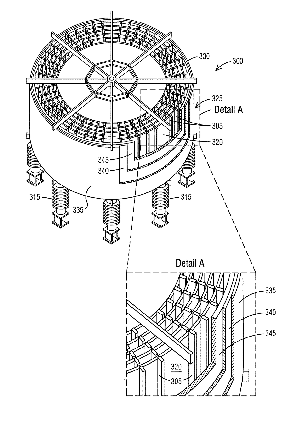
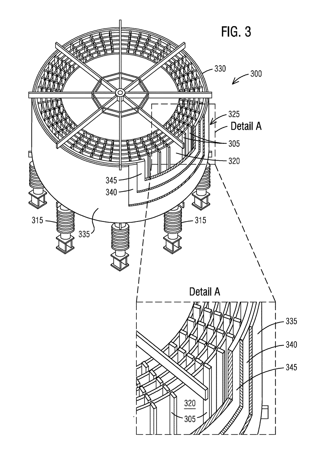
[0016]To facilitate an understanding of embodiments, principles, and features of the present invention, they are explained hereinafter with reference to implementation in illustrative embodiments. In particular, they are described in the context of a projectile resistant cylinder that attaches directly to an outer surface of a coil of windings of an air core reactor to shield it from hostile attacks by providing physical security measures. Embodiments of the present invention, however, are not limited to use in the described devices or methods.

[0017]The components and materials described hereinafter as making up the various embodiments are intended to be illustrative and not restrictive. Many suitable components and materials that would perform the same or a similar function as the materials described herein are intended to be embraced within the scope of embodiments of the present invention.

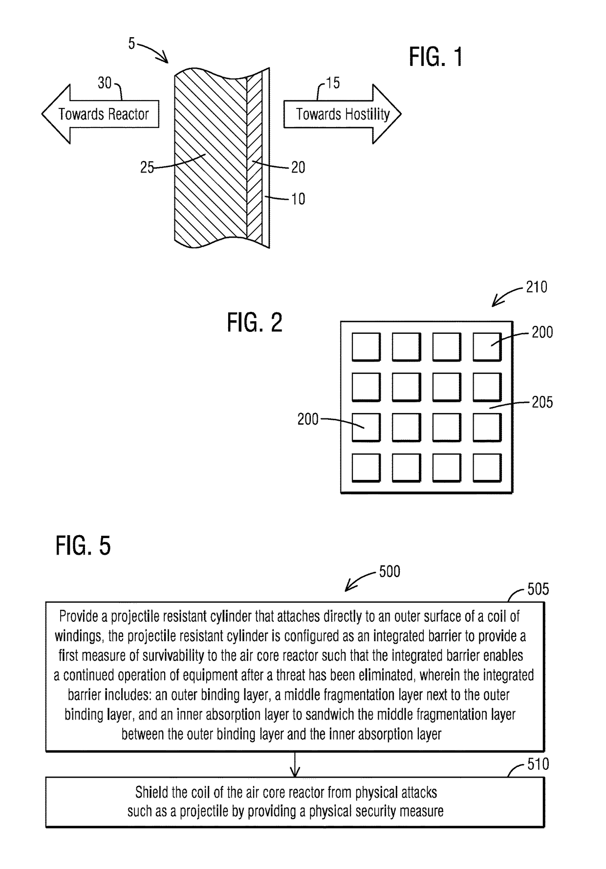
[0018]Consistent with one embodiment of the present invention, FIG. 1 represents a cross sec...


PUM

PropertyMeasurementUnit
disperse energyaaaaaaaaaa
energyaaaaaaaaaa
physical securityaaaaaaaaaa

Abstract

An air core reactor for use in an electric power transmission and distribution system or in an electric power system of an electrical plant is provided. The air core reactor comprises an electrically insulated support structure, an outer surface of a coil of windings configured to operate at a potential and isolated to ground or other potentials by the electrically insulated support structure and a projectile resistant cylinder that attaches directly to the outer surface of the coil of windings. The projectile resistant cylinder is configured as an integrated barrier to provide a first measure of survivability to the air core reactor such that the integrated barrier enables a continued operation of equipment after a threat has been eliminated.

Description

CROSS REFERENCE TO RELATED APPLICATIONS[0001]This application claims the benefit of U.S. Provisional Application Ser. No. 62 / 329,511 entitled “INTEGRATED PROJECTILE BARRIER FOR SUBSTATION EQUIPMENT,” filed on Apr. 29, 2016, the contents of which are hereby incorporated by reference herein in their entirety.BACKGROUND1. Field[0002]Aspects of the present invention generally relate to an integrated barrier for protecting a coil of an air core reactor from a projectile attack and more specifically relate to a projectile resistant cylinder that attaches directly to an outer surface of a coil of windings of an air core reactor to shield it from hostile attacks by providing physical security measures.2. Description of the Related Art[0003]The vulnerability of substations to terrorist attacks is a new phenomenon. Physical attacks on a Bulk-Power System could adversely impact the reliable operation of the Bulk-Power System, resulting in instability, or cascading failures. So entities ought t...

Claims


Application Information

Patent Timeline
Patent Type & Authority Applications(United States)
IPC IPC(8): H01F27/28H01F27/32
CPCH01F27/324H01F27/2885H01F37/005
Inventor KAHN, KAMRAN
Owner TRENCH LTD TRENCH GRP CANADA
Why Eureka
Try Eureka