
Forecasting net load in a distributed utility grid

a technology for utility grids and net load, applied in load forecasting in ac networks, instruments, data processing applications, etc., can solve the problems of utility grids that are significant challenges for energy management systems, non-conformity of net load in that portion of the grid, and low accuracy of electric energy consumption for non-conform loads

Active Publication Date: 2017-11-02
GREEN POWER LABS INC
View PDF7 Cites 50 Cited by
  • Summary
  • Abstract
  • Description
  • Claims
  • Application Information

AI Technical Summary

Benefits of technology

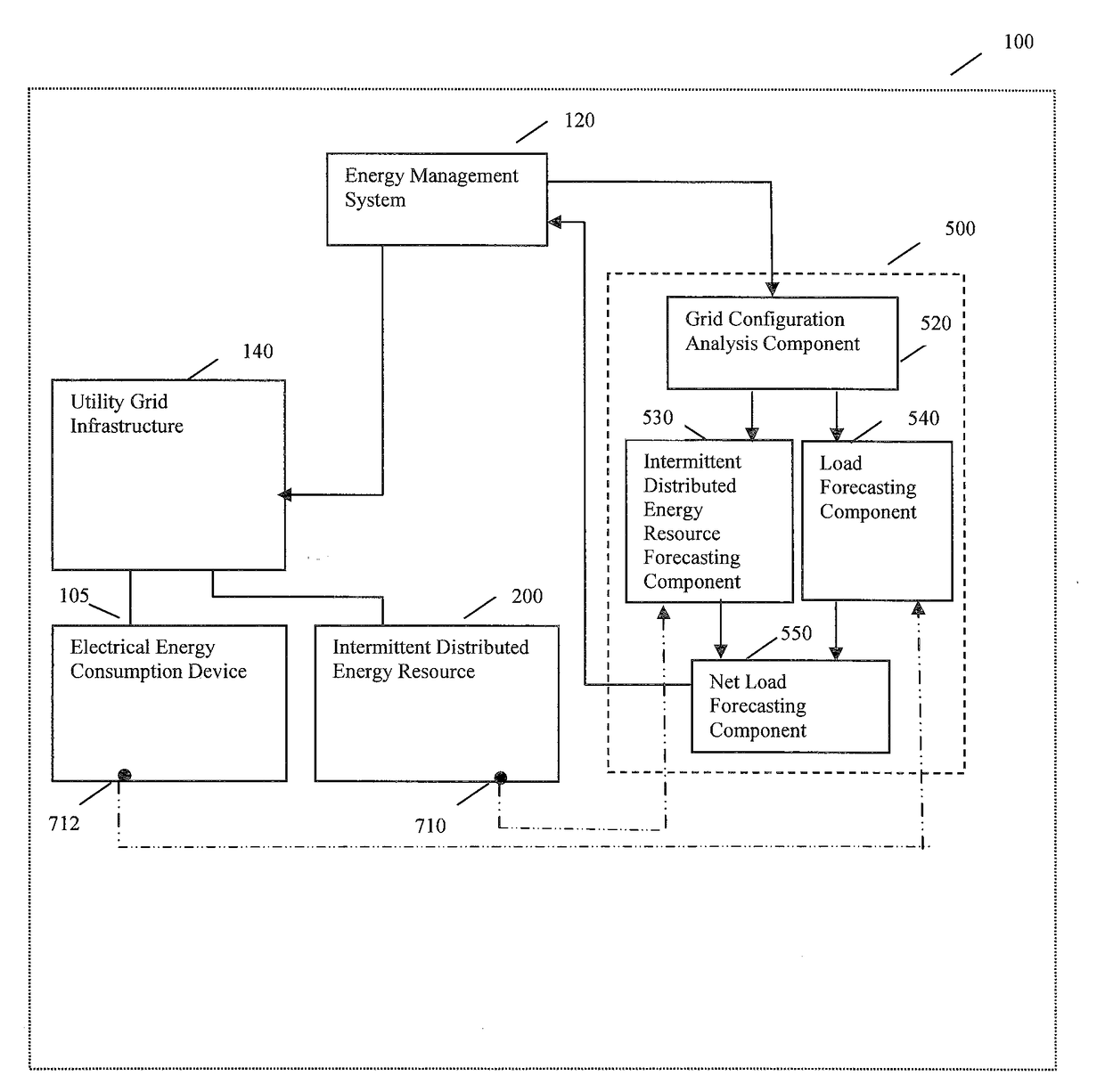
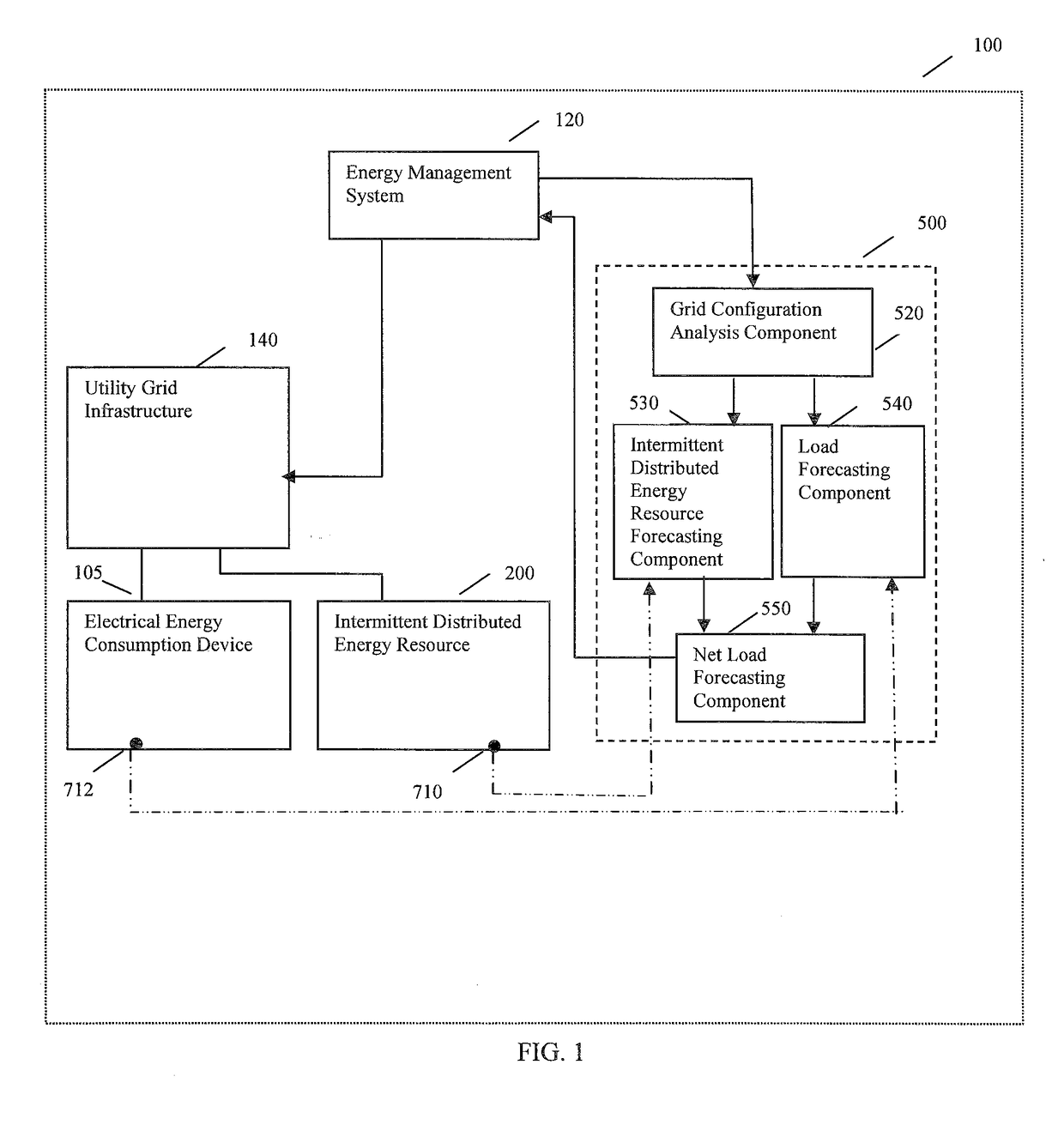
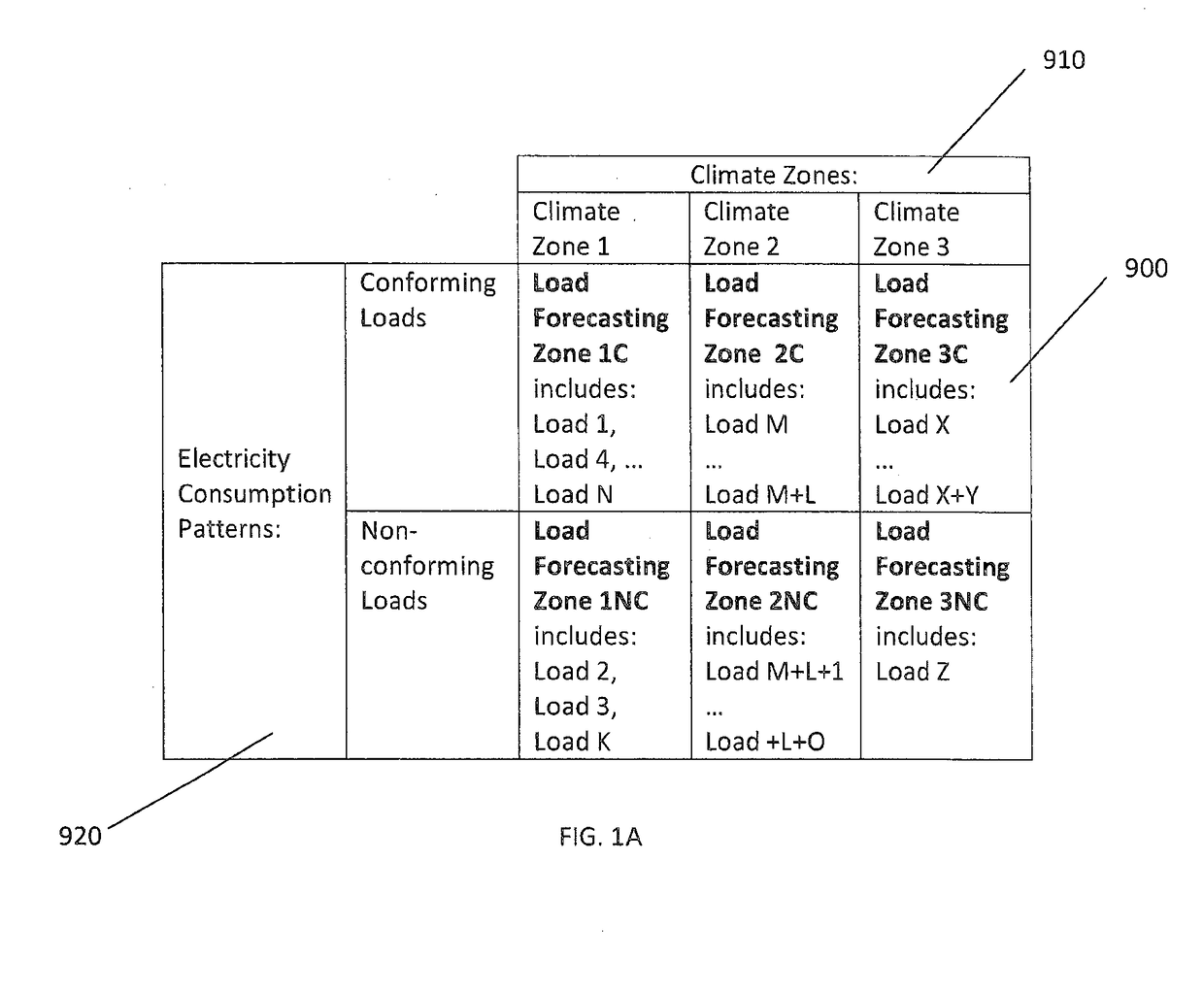
This patent describes a method for predicting the demand for electricity in a utility grid that includes intermittent distributed energy resources and loads. The method involves assigning each load to a specific load forecast zone based on its load profile and climate, and assigning each intermittent distributed energy resource to one or more load forecast zones based on its climate. Each load forecast zone then generates a net load forecast by combining its electrical energy consumption and electric power generation forecasts. This net load forecast is then displayed on a screen. This system helps to improve the grid's efficiency and stability by better managing its energy resources. The patent also includes an apparatus for implementing this method, and articles of manufacture for use in the system.

Problems solved by technology

In contrast, electrical energy consumption for nonconforming loads is typically forecast with lower accuracy.
If the load profile of nonconforming loads are unknown, their presence in a utility grid presents a significant challenge for the energy management system.
As distributed energy resources are typically intermittent by their nature, their presence in a portion of the utility grid makes the net load in that portion of the grid non-conforming.
This creates a significant load forecasting and energy management problem and reduces the energy management system's ability to maintain the grid's stability.

Method used


Image

  • Forecasting net load in a distributed utility grid
  • Forecasting net load in a distributed utility grid
  • Forecasting net load in a distributed utility grid

Examples


Embodiment Construction

[0027]In the following description, details are set forth to provide an understanding of the application. In some instances, certain software, circuits, structures and methods have not been described or shown in detail in order not to obscure the application. The term “data processing system” or “system” is used herein to refer to any machine for processing data, including the net load forecasting systems, control systems, controllers, energy management systems, computer systems, and network arrangements described herein. The present application may be implemented in any computer programming language provided that the operating system of the data processing system provides the facilities that may support the requirements of the present application. Any limitations presented would be a result of a particular type of operating system or computer programming language and would not be a limitation of the present application. The present application may also be implemented in hardware or...


PUM


Abstract

A method for generating a net load forecast for a utility grid, the grid including intermittent distributed energy resources and loads, comprising: defining two or more load forecast zones, each zone being associated with a load profile type and a climate zone type; assigning each of the loads to one of the zones based on the load profile and climate zone types associated with the load; assigning each of the energy resources to at least one of the zones based on the climate zone type associated with the energy resource; for each zone, generating an electrical energy consumption forecast for loads, an electric power generation forecast for energy resources, and a net load forecast from the electrical energy consumption and electric power generation forecasts; combining the net load forecast for each zone to generate the net load forecast for the grid; and, presenting the net load forecast on a display.

Description

[0001]This application claims priority from and the benefit of the filing date of U.S. Provisional Patent Application No. 62 / 068,750, filed Oct. 26, 2014, and the entire content of such application is incorporated herein by reference.FIELD OF THE APPLICATION[0002]This application relates to the field of net load forecasting, and more specifically, to a utility grid, a net load forecasting system, and a method for forecasting net load in a utility grid having distributed energy resources.BACKGROUND OF THE APPLICATION[0003]Load forecasting in a utility grid is an integral part of energy management. Growing penetration of distributed energy resources such as solar photovoltaic (“PV”) power plants, wind power plants, and power storage plants has changed conventional utility practices for generating, transmitting, and distributing electric power.[0004]A group of power plants, electrical energy consumption devices, and associated infrastructure spread over a geographical area may be refer...

Claims


Application Information

Patent Timeline
Patent Type & Authority Applications(United States)
IPC IPC(8): H02J3/06G06Q50/06H02J3/12G06Q10/04G01R22/00H02J3/00
CPCH02J3/06G06Q10/04G06Q50/06G01R22/00H02J2003/003Y04S10/54H02J3/12H02J3/003H02J3/004
Inventor PAVLOVSKI, ALEXANDREANICHKOV, DMITRIY
Owner GREEN POWER LABS INC
Learn More