Method for manufacturing interdental cleaning device

a cleaning device and manufacturing method technology, applied in the field of manufacturing an interdental cleaning device, can solve the problems of difficult to form a non-slip portion or other portion, and raise problems, so as to improve the quality of the interdental cleaning device, prevent poor molding of the cleaning soft portion, and smooth mold the non-slip portion.

Active Publication Date: 2017-11-09
SUNSTAR SUISSE SA
View PDF0 Cites 18 Cited by
  • Summary
  • Abstract
  • Description
  • Claims
  • Application Information

AI Technical Summary

Benefits of technology

[0023]The method according to the present invention for manufacturing an interdental cleaning device includes placing a handle portion in a soft portion molding space and then molding a soft portion on the handle portion. In the step of molding the soft portion, an elastomeric material is supplied to a cleaning portion molding space through a non-slip portion molding space and connecting portion molding spaces. This step is performed by causing a gate of a mold for molding the soft portion to open at a position substantially equally distant from positions of two communicating openings of the non-slip molding space for molding the non-slip portion, the two communicating openings communicating with the connecting portion molding spaces for molding the connecting portions; and charging the elastomeric material from the gate into the soft portion molding space. Therefore, when supplied from the gate to the non-slip portion molding space, the elastomeric material can be supplied simultaneously to the connecting portion molding spaces from the non-slip portion molding space. Therefore, the elastomeric material can be supplied to the cleaning portion molding space at the same timing from the connecting portion molding spaces, which makes it possible to effectively prevent poor molding of the cleaning soft portion and to improve the quality of the interdental cleaning device. In addition, the elastomeric material is charged from the base side of the core portion, which makes it possible to smoothly mold the non-slip portion on the handle portion. In addition, the elastomeric material is charged from the base side of the core portion with a large cross-section, which makes it possible to prevent the core portion from being deformed by heat during the charging of the elastomeric material and to allow the front end portion of the core portion to have a small diameter, so that the length of the cleaning portion insertable between teeth can be made as large as possible to increase the ability to clean the space between teeth. In addition, the interdental cleaning device manufactured by this method has the non-slip portion and the connecting portions, which are formed of the elastomeric material on the handle portion. The non-slip portion and the connecting portions allow the interdental cleaning device to have improved handleability.

Problems solved by technology

Therefore, if the elastomeric material is charged from the base end side to front end side of the core portion during the molding of the cleaning soft portion in the second molding space, poor charging may occur at the front end of the cleaning soft portion.
However, this method raises problems as described below.
When this method is used, the opening area of the gate portion cannot be made large, so that the amount of injection of the elastomer cannot be increased, which can make it impossible to charge a sufficient amount of the elastomeric material into the gripping portion side, make it difficult to form a non-slip portion or other portions on the gripping portion, and lead to a quick decrease in the temperature of the charged elastomer.
In this method, therefore, it can be difficult to bond the elastomeric material to the synthetic resin of the core portion, so that the non-slip portion may easily peel off.
In order to prevent the front end of the core portion from being softened and deformed, this method also forces the core portion to have a large diameter, which can make it impossible to insert the cleaning portion between teeth or can reduce the length of the cleaning portion insertable between teeth, so that sufficient cleaning ability cannot be obtained.

Method used


Image

  • Method for manufacturing interdental cleaning device
  • Method for manufacturing interdental cleaning device
  • Method for manufacturing interdental cleaning device

Examples


Embodiment Construction

Interdental Cleaning Device

[0040]First, the configurations of an interdental cleaning device 1 will be described.

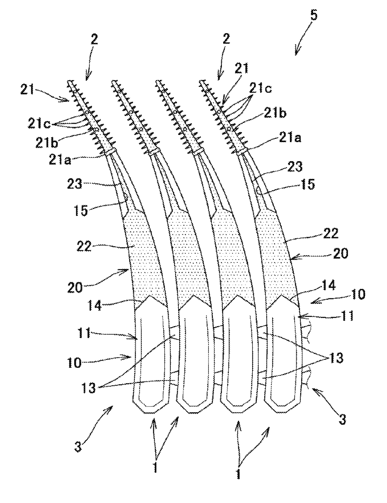
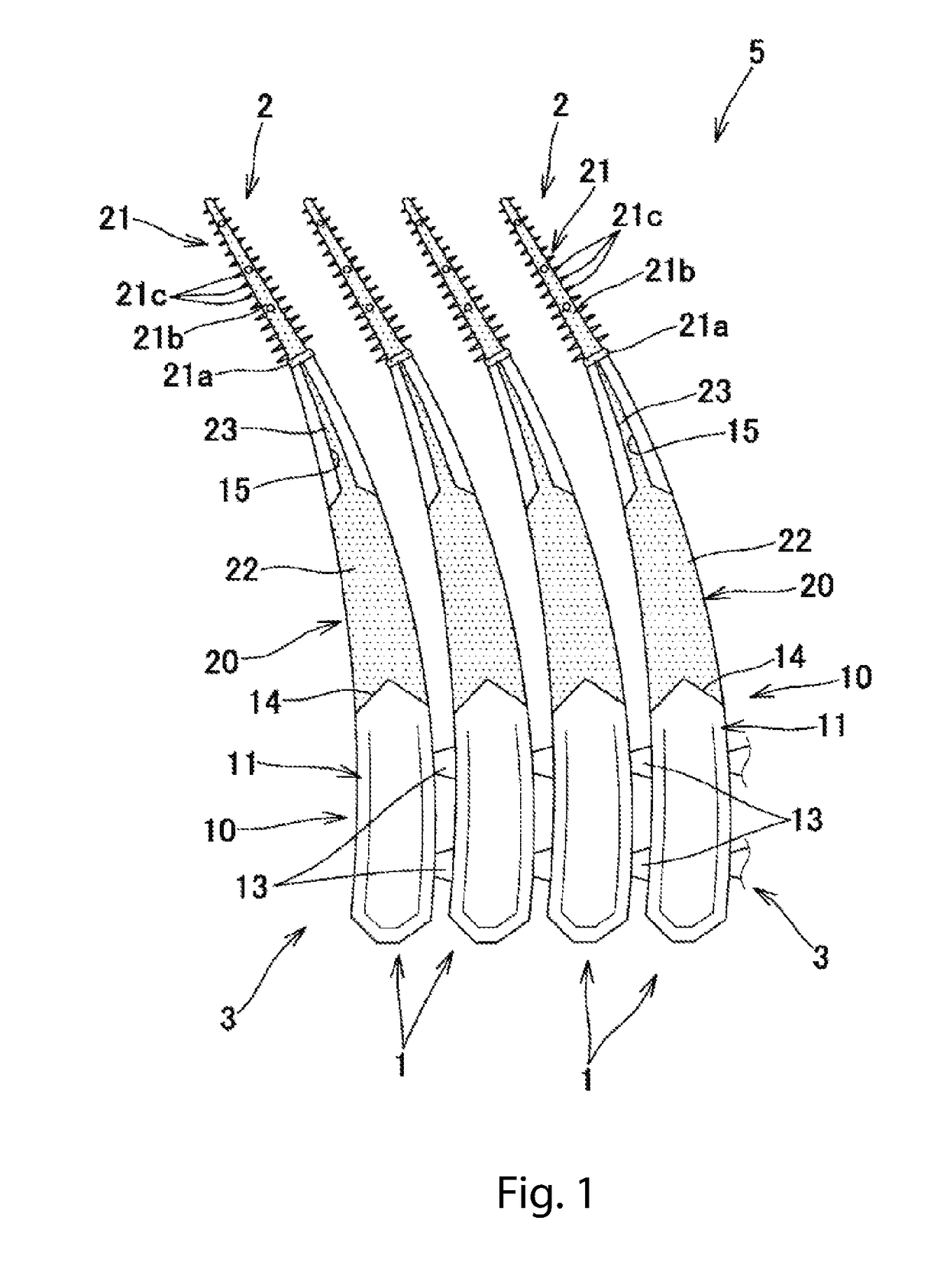
[0041]As illustrated in FIGS. 1 and 2, the interdental cleaning device 1 includes a cleaning portion 2 for interdental cleaning and a gripping portion 3 as a handle, which are distinguishable in terms of function, and also includes a base portion 10 including a synthetic resin and a soft portion 20 including an elastomeric material, which are distinguishable in terms of material. The interdental cleaning devices 1 are manufactured in the form of an interdental cleaning device chain 5, which includes a plurality of interdental cleaning devices 1 separably connected in parallel to one another. The user will use each interdental cleaning device 1 by disconnecting one by one the interdental cleaning devices 1 at connecting protrusions 13 from one side of the interdental cleaning device chain 5. The number of connected interdental cleaning devices 1 in the interdental cleaning...


PUM

PropertyMeasurementUnit
lengthaaaaaaaaaa
thicknessaaaaaaaaaa
thicknessaaaaaaaaaa

Abstract

Provided is a method for manufacturing an interdental cleaning device (1) including a base portion (10) having a handle portion (11) and a core portion (12); and a soft portion (20) having a cleaning soft portion (21), a non-slip portion (22), and connecting portions (23) extending from two sites of the non-slip portion (22) and being connected to the cleaning soft portion (21). The method includes causing a second gate (49) of second molds (40) and (41) for molding the soft portion (20) to open at a position substantially equally distant from positions of two communicating openings (48a) of a non-slip molding space (47) for molding the non-slip portion (22), the two communicating openings (48a) communicating with connecting portion molding spaces (48) for molding the connecting portions (23); and charging the elastomeric material from the second gate (49) into a second molding space (42) for molding the soft portion (20) to fill the molding space (42).

Description

TECHNICAL FIELD[0001]The present invention relates to a method for manufacturing an interdental cleaning device having an elastomer-covered cleaning portion.BACKGROUND ART[0002]An interdental cleaning device in actual use includes a base portion made of a synthetic resin and a soft portion made of an elastomer, in which the base portion includes a handle portion and a core portion provided at the front end of the handle portion and having a slender shaft shape, the soft portion includes a cleaning soft portion covering the core portion, the handle portion forms a gripping portion as a grip, and the core portion and the cleaning soft portion form a cleaning portion for cleaning between teeth (see, e.g., Patent Literatures 1 to 3).[0003]A method widely used to manufacture this interdental cleaning device includes charging a synthetic resin material into a first molding space of first molds to form a base portion; placing, in a second molding space of second molds, the base portion mol...

Claims


Application Information

Patent Timeline
Patent Type & Authority Applications(United States)
IPC IPC(8): A61C15/02B29C45/16B29K21/00B29L31/42
CPCA61C15/02B29L2031/425B29K2021/006B29C45/1676A46B15/0093A46D3/00A46B2200/108B29C45/14622B29C45/125B29C45/2735B29C45/2626B29C45/14336
Inventor GENGYO, ANRIKATO, KEISUKEBUTZ, JURGEN
Owner SUNSTAR SUISSE SA
Why Eureka
Try Eureka