Piezoelectric energy harvester

a technology of energy harvester and piezoelectric, which is applied in piezoelectric/electrostrictive/magnetostrictive devices, piezoelectric/electrostriction/magnetostriction machines, electrical equipment, etc., can solve the problem that the electricity generated by the energy harvester cannot be supplied to electronic devices with large power consumption for use, and achieve the effect of generating electricity

Active Publication Date: 2017-11-09
CHUNG YUAN CHRISTIAN UNIVERSITY
View PDF6 Cites 10 Cited by
  • Summary
  • Abstract
  • Description
  • Claims
  • Application Information

AI Technical Summary

Benefits of technology

[0005]In the piezoelectric energy harvester of the present invention, the arc-shaped piezoelectric elements are situated on the arc-shaped metal stands. When the arc-shaped metal stands are forced to deform such that the arc-shaped piezoelectric elements deform, the mechanical energy can be converted into electricity through the piezoelectric effect. According to an embodiment of the present invention, the piezoelectric energy harvester of the present invention can be provided in the heel. With each walk, the compression to the heel caused by the user's foot enables the piezoelectric energy harvester to generate electricity.

Problems solved by technology

In consideration of the current development of energy harvesting technology, the electricity generated by an energy harvester cannot be supplied to electronic devices with large power consumption for use.
However, with the rapid development of science and technology and environmental issues gradually being taken seriously, the potential technology development of the energy harvester is still worthy of further research and development.

Method used


Image

  • Piezoelectric energy harvester
  • Piezoelectric energy harvester
  • Piezoelectric energy harvester

Examples


first embodiment

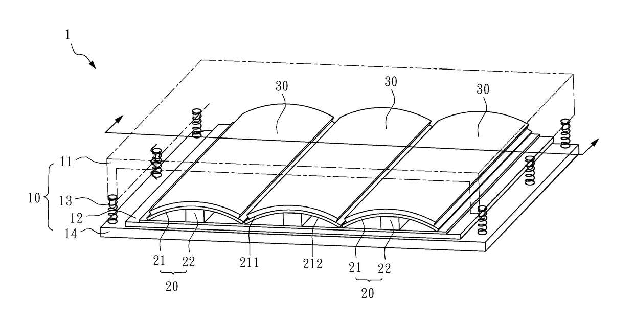
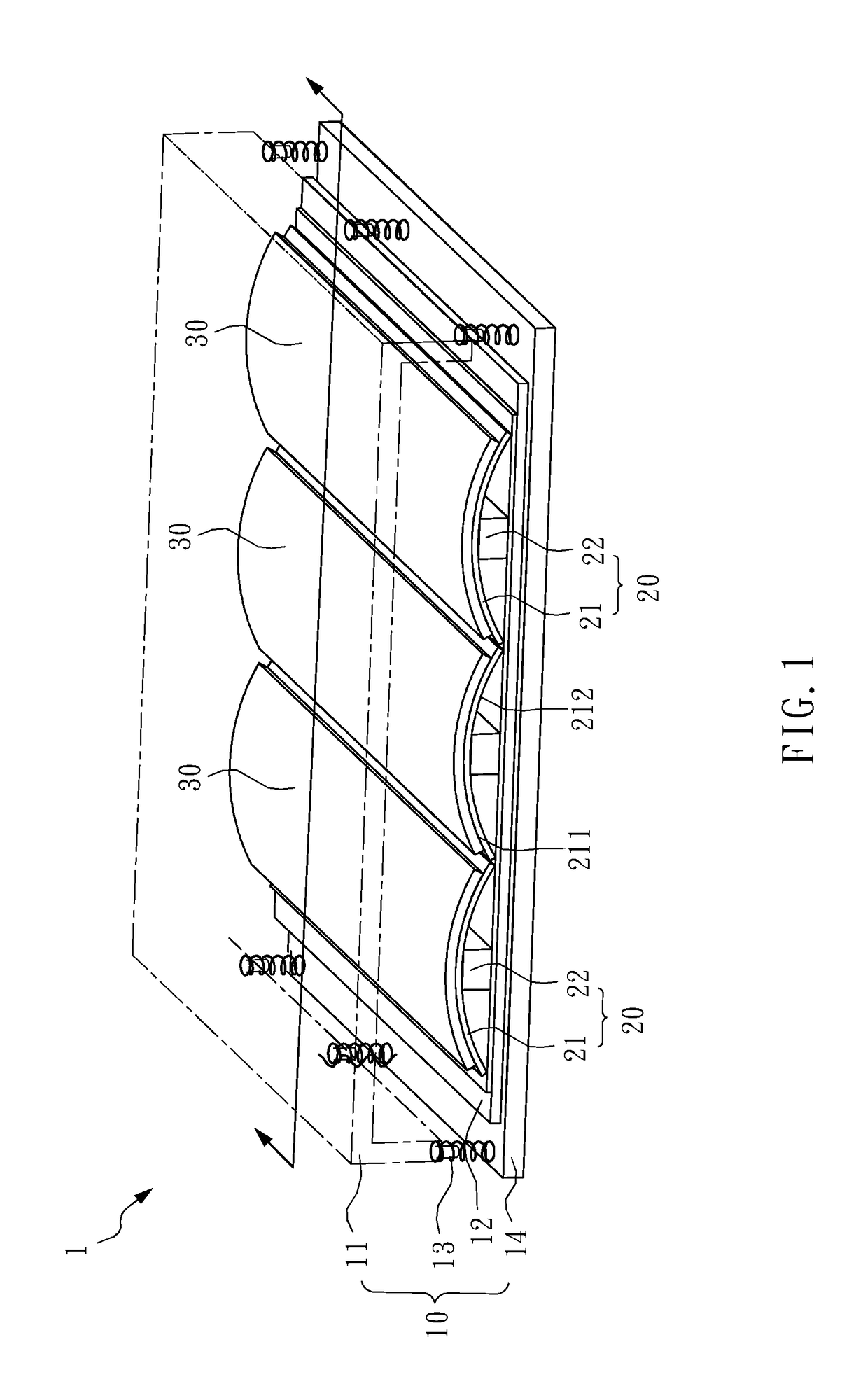
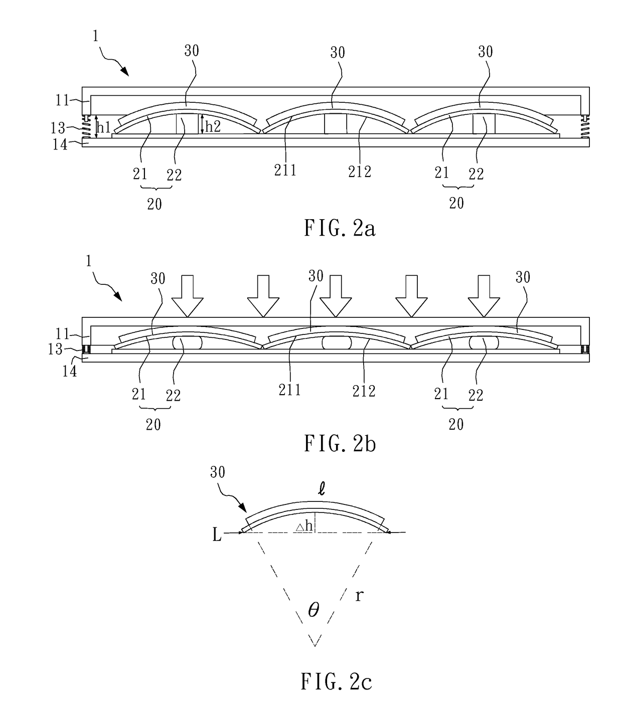
[0014]Hereafter, the technical content of the present invention will be better understood with reference to preferred embodiments. Please refer to FIGS. 1, 2a and 2b for a schematic drawing of a piezoelectric energy harvester according to the present invention, a cross-sectional drawing of the piezoelectric energy harvester, and a cross-sectional drawing when the piezoelectric energy harvester is compressed by an external force.

[0015]As shown in FIGS. 1, 2a and 2b, a piezoelectric energy harvester 1 in the present invention includes a box 10, a plurality of first arc-shaped metal stands 20, and a plurality of arc-shaped piezoelectric elements 30, wherein the plurality of first arc-shaped metal stands 20 is situated in the box 10. Each of the arc-shaped piezoelectric elements 30 is situated on each of the first arc-shaped metal stands 20. When an external force is applied to the box 10, the plurality of first arc-shaped metal stands 20 are compressed to deform, such that the pluralit...

second embodiment

[0025]Hereafter, please refer to FIG. 5, which is a schematic drawing showing the use state of the piezoelectric energy harvester according to the present invention. As shown in FIG. 5, a specific application of the piezoelectric energy harvester 1a in the present invention is a heel of a shoe 90. With each walk, the arc-shaped piezoelectric elements 30 are deformed to generate electricity due to the compression of the heel (piezoelectric energy harvester 1a) caused by the user's foot. It should be noted here that the piezoelectric energy harvester 1 may also be used as a heel. FIG. 5 is illustrative only.

[0026]The plurality of arc-shaped piezoelectric elements 30 adapted by the piezoelectric energy harvester 1 and 1a in the present invention can boost the energy harvesting efficiency. Further, the size of the piezoelectric energy harvester 1 and 1a can be designed according to usage requirements. Even in the limited space inside the heel, through the structure where the arc-shaped ...


PUM


Abstract

A piezoelectric energy harvester has a box, a plurality of first arc-shaped metal stands and a plurality of arc-shaped piezoelectric elements. The box has an upper portion, a connection base, a buffer element and a lower portion. The connection base situates between the upper portion and the lower portion. The upper portion movably connects with the lower portion through the buffer element. The plurality of first arc-shaped metal stands situated on a side of the connection base in the box. Each of the arc-shaped piezoelectric elements locates on each of the first arc-shaped metal stands. When an external force applied on the box, the plurality of first arc-shaped metal stands deforms due to the compression from the upper portion and consequently causes the deformation of the arc-shaped piezoelectric elements for generating electricity accordingly.

Description

BACKGROUND OF THE INVENTION1. Field of the Invention[0001]The present invention relates to a piezoelectric energy harvester, particularly to a piezoelectric energy harvester having a plurality of arc-shaped piezoelectric elements.2. Description of the Related Art[0002]An energy harvester gathers surrounding energy, converts the energy into electricity, and provides the electricity to an electronic device connected therewith. For example, a solar panel that converts light energy into electricity is a kind of energy harvester. In consideration of the current development of energy harvesting technology, the electricity generated by an energy harvester cannot be supplied to electronic devices with large power consumption for use. However, with the rapid development of science and technology and environmental issues gradually being taken seriously, the potential technology development of the energy harvester is still worthy of further research and development.SUMMARY OF THE INVENTION[000...

Claims


Application Information

Patent Timeline
Patent Type & Authority Applications(United States)
IPC IPC(8): H01L41/113H01L41/053
CPCH01L41/053H01L41/113H02N2/18A43B3/38H10N30/30H10N30/88
Inventor TING, YUNGLIN, SHEUAN-PERNGYU, CHIH-HSUANWANG, CHIEN-WEN
Owner CHUNG YUAN CHRISTIAN UNIVERSITY
Why Eureka
Try Eureka