
Electrical connectors

Active Publication Date: 2017-11-09
FOXCONN INTERCONNECT TECHNOLOGY LIMITED
View PDF11 Cites 6 Cited by
  • Summary
  • Abstract
  • Description
  • Claims
  • Application Information

AI Technical Summary

Benefits of technology

The present invention is a receptacle connector that has a better design for its lead-frame assembly. The technical effect of this improvement is that it makes the connector more reliable and durable.

Problems solved by technology

The four of the contacts of each column of the four row contacts are difficult to be molded in a common insulative frame that will increase the assembling steps.

Method used


Image

  • Electrical connectors
  • Electrical connectors
  • Electrical connectors

Examples


Embodiment Construction

[0028]Reference will now be made in detail to the preferred embodiment of the present invention.

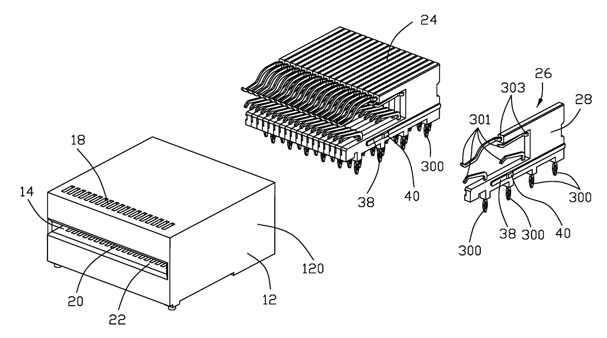
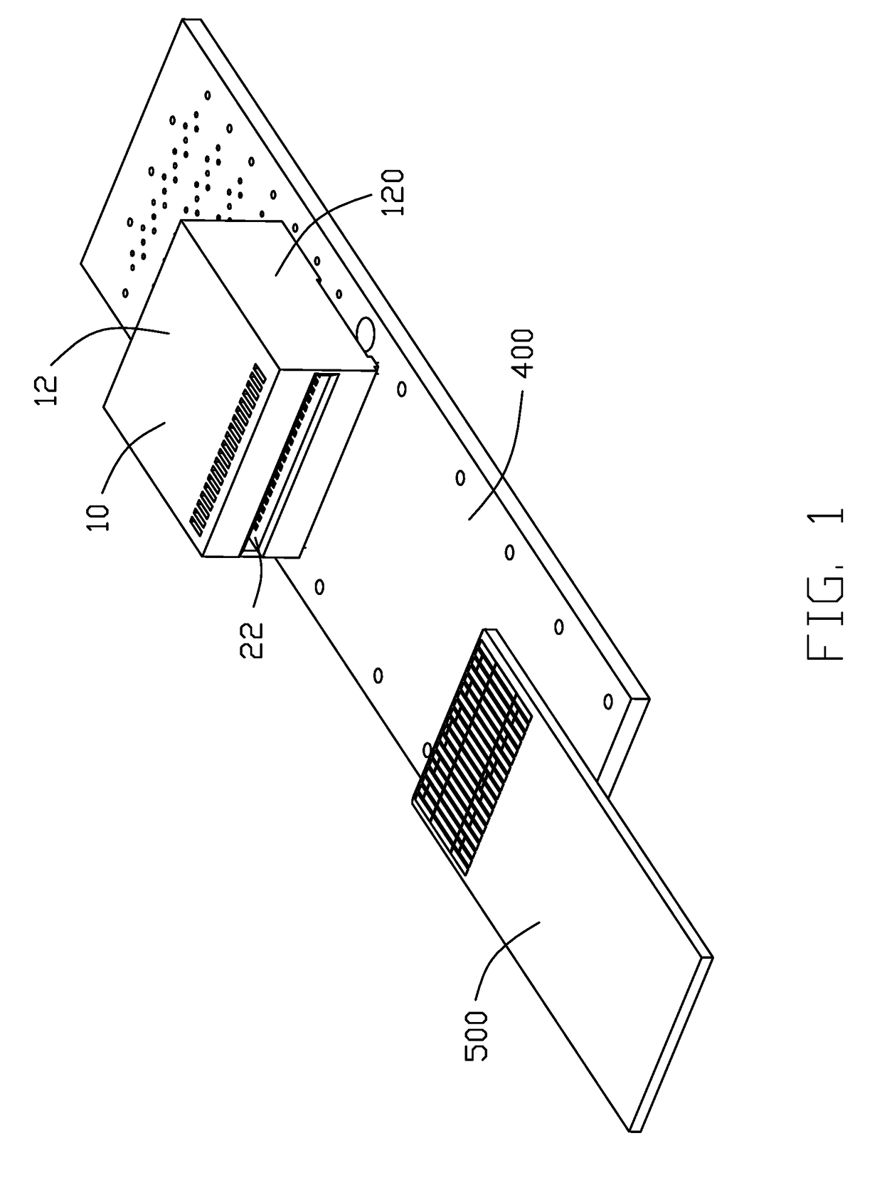
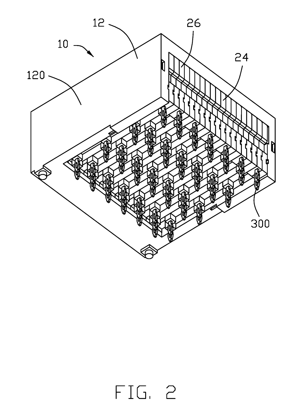
[0029]Referring to FIGS. 1-8, an electrical connector assembly 1 comprises an inner printed circuit board 500 of a plug connector (FIG. 20), and a receptacle connector 10 mounted upon an outer mother board 400. The receptacle connector 10 includes an insulative housing 12 defining a front mating port 14 and a rear connecting port 16. A plurality of upper passageways 18 and a plurality of lower passageways 20 with a receiving slot 22 therebetween in the vertical direction for receiving the printed circuit board 500, are formed in the front mating port 14. The insulative housing 12 comprises a pair of side walls 120, at least one of the side walls 120 defining an engagement groove 121 with a recession 122 in an inner side. An IMLA (Insert Molded Lead-Frame Assembly) 24 is received within a space (not labeled) in the rear connecting port 16.

[0030]The IMLA 24 includes a plurality of wafers 26...


PUM


Abstract

A receptacle connector for two types of plug includes an insulative housing defining a front mating port and a rear connecting port along the front-to-back direction, the front mating port defining a plurality of upper passageways and a plurality of lower passageways with a receiving slot therebetween in the vertical direction, the upper passageways being respectively offset from the corresponding lower passageways in a transverse direction. An IMLA (Insert Molded Lead-Frame Assembly) assembled within a space of the rear connecting port and including a plurality of wafers stacked with one another along the transverse direction, each of said wafers including an insulator equipped with a front upper contact disposed in the corresponding upper passageway, a rear upper contact located behind the corresponding upper passageway, a front lower contact disposed in the corresponding lower passageway, and a rear lower contact located behind the corresponding lower passageway.

Description

BACKGROUND OF THE INVENTION1. Field of the Invention[0001]The invention relates to electrical connectors, and particularly to the hybrid type QSFP including the Legacy QSFP 28 and QSFP-DD interfaces.2. Description of Related Art[0002]For the QSFP connector, the trend leads to the two rows arrangement on the memory card (of the plug connector) with the QSFP-DD in an outer row and the Legacy QSFP 28 in the inner row. The corresponding receptacle is required to be rearranged corresponding to such a hybrid type QSFP. U.S. Publication No. US20070232091, published to Liu on Oct. 4, 2007, discloses a receptacle connector mated with a plug connector. The receptacle connector comprises a body, a row of upper front contacts, received in the body, a row of rear upper contacts disposed behind the upper front contacts, a row of lower front contacts received in the body, and a row of lower rear contacts disposed behind the lower front contacts. The plug connector comprises a printed circuit board...

Claims


Application Information

Patent Timeline
IPC IPC(8): H01R27/00H01R13/514H01R24/60H01R12/72H01R107/00
CPCH01R27/00H01R24/60H01R2107/00H01R13/514H01R12/721H01R12/70H01R13/405H01R13/506H01R12/716H01R13/02H01R13/502H01R13/665H01R12/724H01R24/62H01R25/006H01R27/02
Inventor LITTLE, TERRANCE F.
Owner FOXCONN INTERCONNECT TECHNOLOGY LIMITED
Learn More