Ice rink illumination

a technology of ice rinks and illuminants, applied in the field of illumination of ice rinks, can solve the problems that the melting of commercially available illuminants into ice rinks does not lead to satisfactory results in many applications, and achieves the effect of simplifying the relative positioning of the light sources of the illuminant arrangemen

Active Publication Date: 2017-11-16
HS TECHNICS
View PDF6 Cites 5 Cited by
  • Summary
  • Abstract
  • Description
  • Claims
  • Application Information

AI Technical Summary

Benefits of technology

[0069]Thereby, the first or the second or also the first and the second connecting elements can serve for a stabilisation of a relative position of the light sources to one another in a direction perpendicular to the surface.
[0070]An incorporatio

Problems solved by technology

The inventor has recognised that a melting of commercially available illuminants arrangements into ice rinks does not lead to sa

Method used


Image

  • Ice rink illumination
  • Ice rink illumination
  • Ice rink illumination

Examples


Embodiment Construction

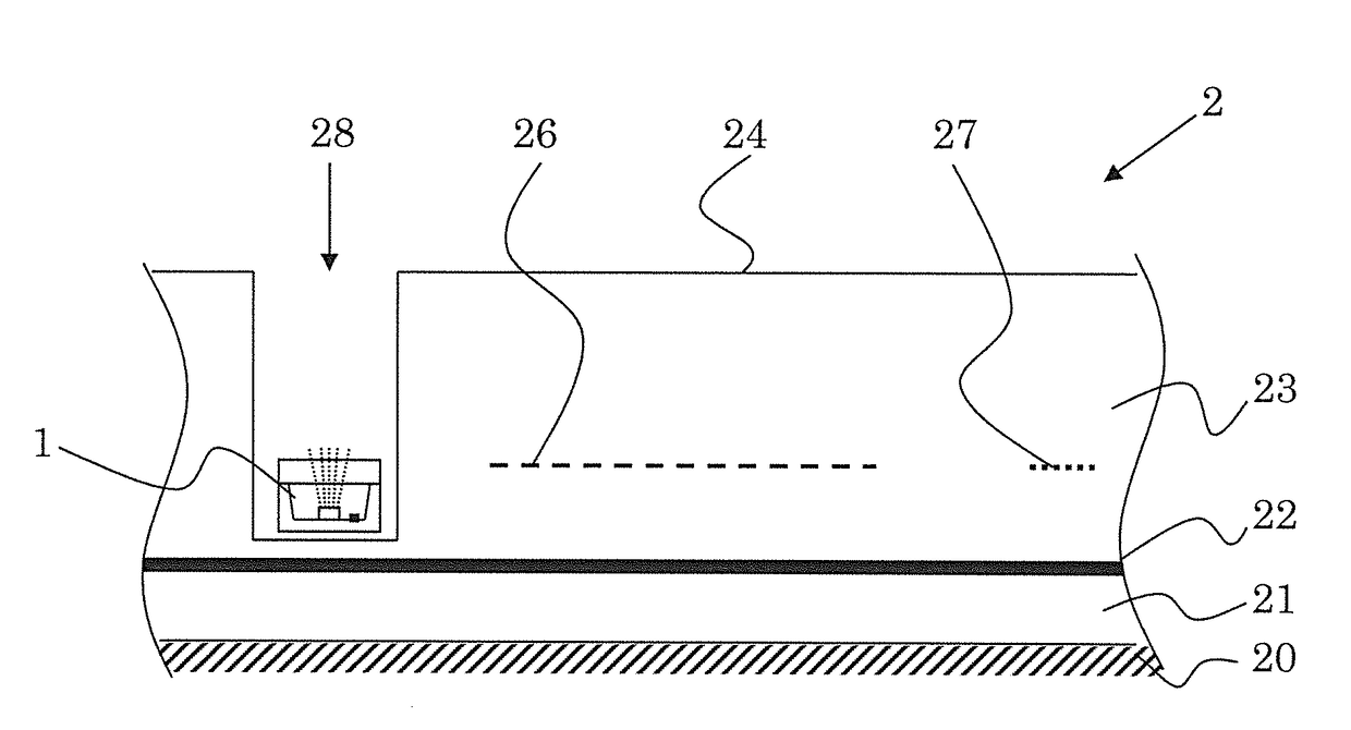
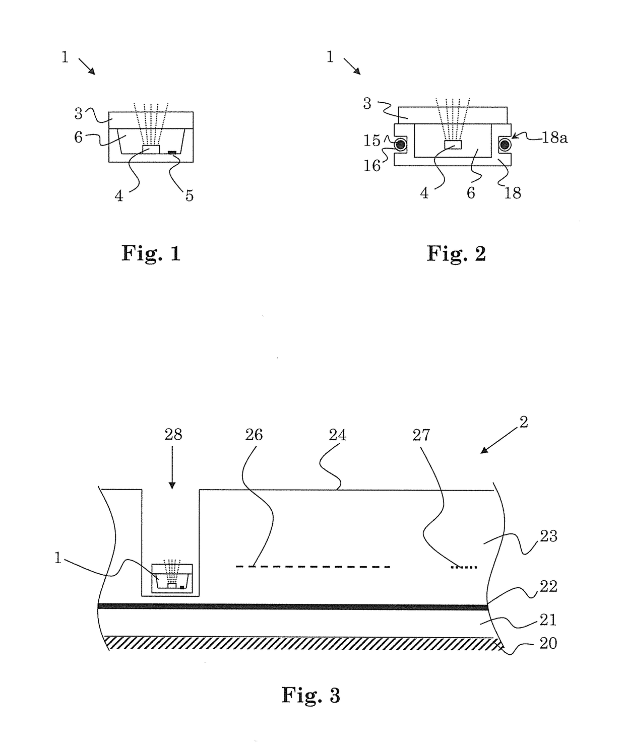
[0142]Parts which are not essential to the understanding of the invention are not represented to some extent. The described embodiment examples represent the subject-matter of the invention by way of example or they serve for its explanation and have no limiting effect

[0143]A section through the illuminants arrangement 1 is represented schematically in FIG. 1. The illuminants arrangement 1 can be embodied for example in a strip-shaped manner with a multitude of light sources, wherein the respective strip runs perpendicular to the plane of the drawings.

[0144]What is represented in FIG. 1 are: a light source 4, a connection lead 5, a water-tight encasing 6, a housing part 6′, which can contribute to the encasing of the light source 4, and a protective overlay 3.

[0145]The light source 4 is controllable and / or can be supplied with electrical voltage via a connection lead 5.

[0146]The light source can, e.g., include a red-illuminating, a green-illuminating and a blue-illuminating LED, and...


PUM

PropertyMeasurementUnit
Lengthaaaaaaaaaa
Lengthaaaaaaaaaa
Lengthaaaaaaaaaa

Abstract

The illuminants arrangement includes a plurality of LED-based light sources that are encased in a water-tight manner by way of one or more encasings, wherein the light sources are, at least in a group-wise manner, operationally interconnected by way of electrical connection leads. The connection leads include voltage supply leads. The illuminants arrangement as a protection of the one or more encasings and the light sources from mechanical damage includes at least one protective overlay for being placed onto the one or more encasings, so that light emitted by the light sources can be emitted through the at least one protective overlay. The illuminants arrangement can include a heating device. Each of the light sources can be suitable for emitting light of a variable color, wherein the color of each of the light sources can be individually selected by way of a control unit.

Description

BACKGROUND OF THE INVENTIONField of the Invention[0001]The invention on the one hand relates to the field of illumination technology and on the other hand to ice rinks, in particular ice rinks which form playing fields, in particular for ice hockey sports.Description of Related Art[0002]The possibility of illumination tubes being able to be frozen into ice slabs, so as to permit monochromic light lines to appear in the ice, is known, for example, for disco events.[0003]It is also known to project advertising banners onto the surface of the ice of the ice rink by way of projectors attached above the ice rink, during pauses or breaks in ice hockey matches.[0004]Moreover, it is known to realise playing field markings in the form of felt strips that are incorporated into an ice rink.SUMMARY OF THE INVENTION[0005]The inventor has recognised that a melting of commercially available illuminants arrangements into ice rinks does not lead to satisfactory results in many applications, in parti...

Claims


Application Information

Patent Timeline
IPC IPC(8): A63C19/10F21V23/00F21V23/06F21V29/90F21V3/04F21V31/00
CPCA63C19/10F21V31/00F21V23/06F21V3/0436F21V29/90F21V23/003A63C2203/14F21Y2115/10F21Y2105/10F21Y2103/10F21Y2113/13F21V3/062
Inventor SCHLEUNIGER, ROMAN
Owner HS TECHNICS
Why Eureka
Try Eureka