Vertical take-off and landing aircraft with hybrid power and method

a technology of vertical take-off and landing and hybrid power, applied in the field of rotorcraft, can solve the problems of affecting the desirable endurance of the aircraft, requiring more power from the engine, and requiring a long enduran

Inactive Publication Date: 2017-11-16
SIKORSKY AIRCRAFT CORP
View PDF43 Cites 114 Cited by
  • Summary
  • Abstract
  • Description
  • Claims
  • Application Information

AI Technical Summary

Benefits of technology

[0016]In addition to one or more of the features described above or below, or as an alternative, further embodiments could include the third power system including at least one solar panel disposed at least partially on the wing structure.
[0017]In addition to one or more of the features described above or below, or as an alternative, further embodiments could include the wing as a first wing, and the rotor as a first rotor, and further including a fuselage, a second wing, the first and second wings extending outwardly from opposite sides of the fuselage, a first nacelle supported on the first wing, the first rotor operatively configured on the first nacelle, a second nacelle supported on the second wing, and a second rotor operatively configured on the second nacelle.
[0018]In addition to one or more of the features described above or below, or as an alternative, further embodiments could include the first power system at least partially disposed in the first nacelle, the second power system at least partially disposed in the second nacelle, and at least one of the first and second energy sources at least partially disposed in the fuselage.
[0019]In addition to one or more of the features described above or below, or as an alternative, further embodiments could include a first gearbox of the first rotor, a second

Problems solved by technology

However, during take-off or hover, the VTOL aircraft requires more power from the engines than is required during long-range cruise (i.e., wing borne flight).
However, operating both engines during cruise can n

Method used


Image

  • Vertical take-off and landing aircraft with hybrid power and method
  • Vertical take-off and landing aircraft with hybrid power and method
  • Vertical take-off and landing aircraft with hybrid power and method

Examples


Embodiment Construction

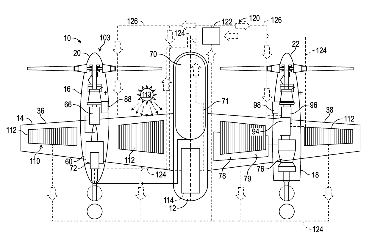
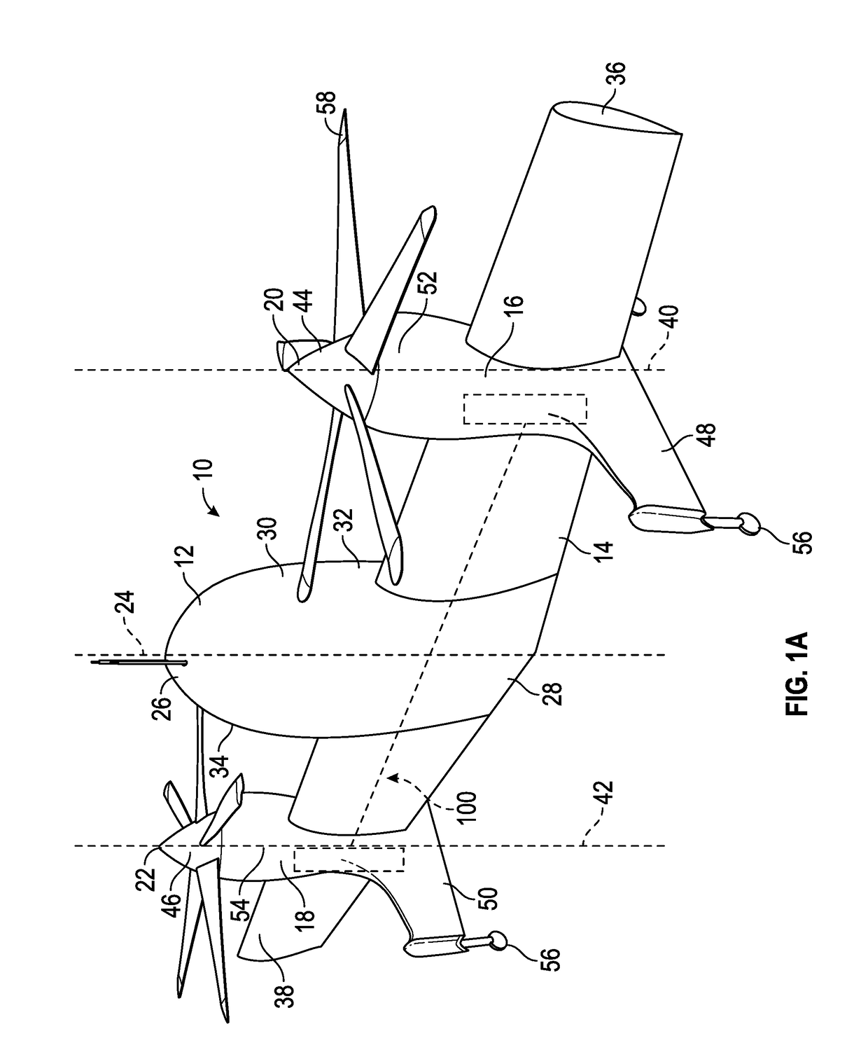
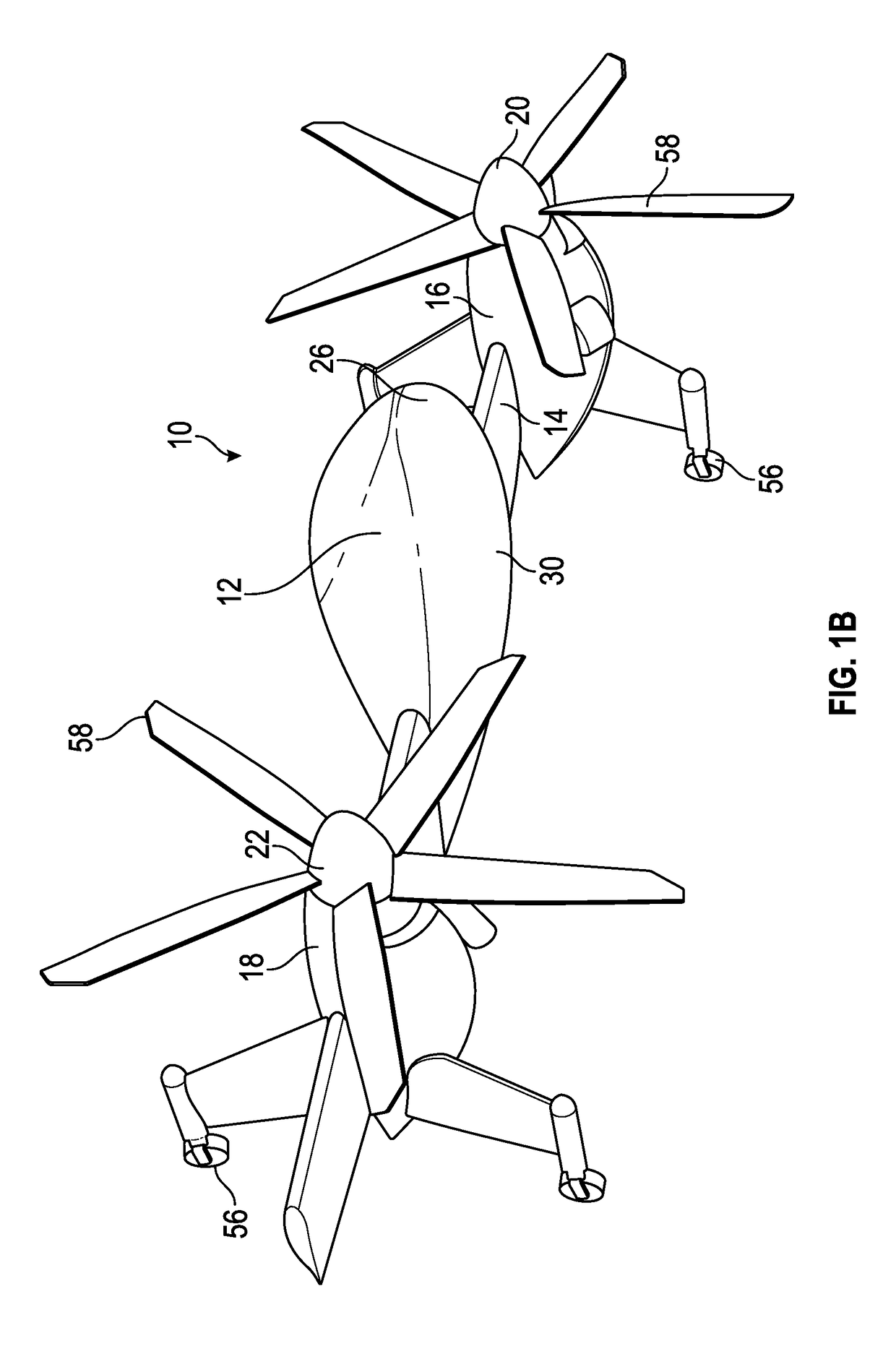
[0033]Referring now to the drawings, FIGS. 1A and 1B illustrate perspective views of an embodiment of a VTOL vehicle in the form of a tail-sitter aircraft 10 for providing high speed, and endurance flight. As illustrated, tail-sitter aircraft 10 includes a fuselage 12, an elongated wing structure 14, a plurality of nacelles 16, 18, and a plurality of rotors 20, 22. FIG. 1A shows an embodiment of the aircraft 10 as it may be orientated during take-off (or hover) in a rotor-borne flight state, where longitudinal axis 24 of fuselage 12 is oriented in a vertical direction and may be substantially perpendicular with respect to a ground plane. FIG. 1B shows an embodiment of the aircraft 10 during a cruise (wing-borne flight), where the wing structure 14 and fuselage 12 can be substantially parallel to the ground plane. The fuselage 12 is generally located in the middle of wing structure 14. The fuselage 12 may have an aerodynamic shape with a nose section 26, a trailing end 28 opposite fr...


PUM


Abstract

A vertical take-off and landing aircraft including a wing structure including a wing, a rotor operatively supported by the wing, and a hybrid power system configured to drive the rotor, the hybrid power system including a first power system and a second power system, wherein a first energy source for the first power system is different than a second energy source for the second power system.

Description

CROSS REFERENCE TO RELATED APPLICATIONS[0001]This application claims the benefit of an earlier filing date from U.S. Provisional Application Ser. No. 62 / 266,552 filed Dec. 11, 2015, the entire disclosure of which is incorporated herein by reference.BACKGROUND[0002]The subject matter disclosed herein relates generally to the field of rotorcraft, and more particularly to a vertical take-off and landing (VTOL) aircraft with a power system that balances and maximizes take-off and endurance performance.[0003]Typically, a VTOL aircraft, such as a helicopter, tiltrotor, tiltwing, or a tail-sitter aircraft, can be airborne from a relatively confined space. Unmanned aerial vehicles (UAV's), for example, fixed-wing, and rotorcraft UAV's are powered aircraft without a human operator. Autonomous UAV's are a natural extension of UAV's and do not require real-time control by a human operator and may be required to operate over long distances during search and / or rescue operations or during intell...

Claims


Application Information

Patent Timeline
IPC IPC(8): B64C29/02B64D27/12H02S40/38H01M8/04082H01M10/46H01M8/04007B64D27/24B64D27/02
CPCB64C29/02H01M8/04007B64D27/12B64D27/24H02S40/38H01M8/04201H01M10/465B64D2211/00B64D2027/026H01M2250/20H01M2250/402H01M2250/407B64D35/02B64D35/08B64D2041/005H02S20/00Y02E10/50Y02E60/10Y02E60/50Y02E70/30Y02T50/50Y02T50/60Y02T90/40
Inventor ALBER, MARK R.
Owner SIKORSKY AIRCRAFT CORP
Why Eureka
Try Eureka