Passive Device Designed to Facilitate Demise of A Space System During Re-Entry Into the Earth's Atmosphere
- Summary
- Abstract
- Description
- Claims
- Application Information
AI Technical Summary
Benefits of technology
Problems solved by technology
Method used
Image

Examples
first embodiment
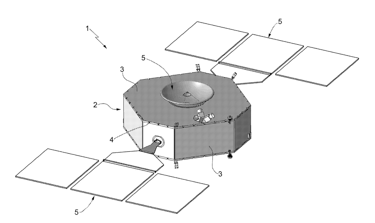
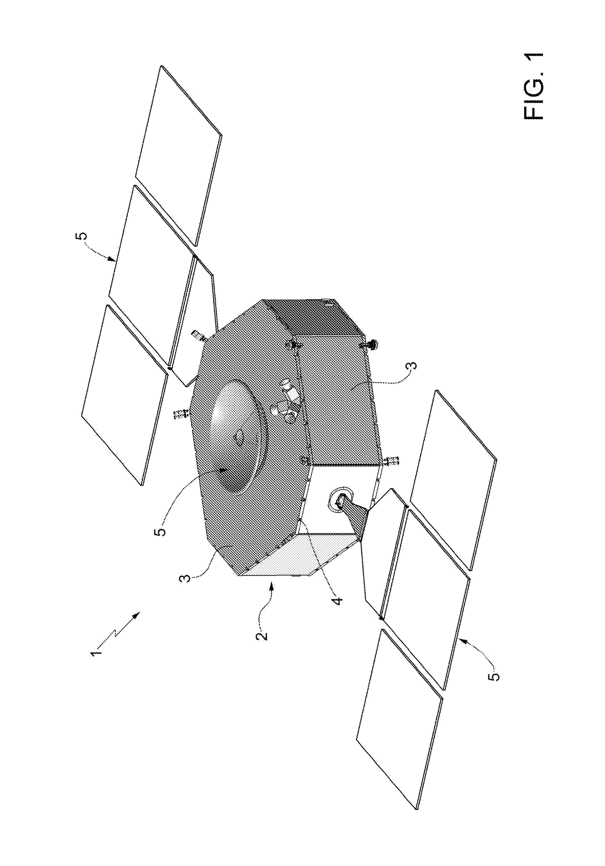
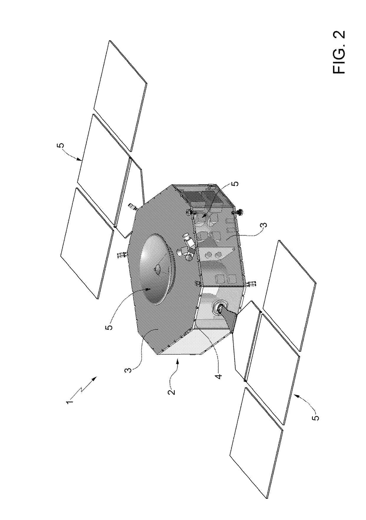
[0033]According to the invention, each connecting member 4 is mounted to exert between a pair of panels 3 a stable connection force in a given connection direction during launch and orbit operation of the satellite 1, and to enable the two panels 3 to disengage from each other by sliding in a direction transverse to the coupling direction during the satellite re-entry into the Earth's atmosphere.
[0034]A possible implementation of this first embodiment is shown in FIGS. 4 to 6, wherein each connecting member 4 comprises two structural elements 6, 7 made of metal, hereinafter referred to as inserts, which are stably coupled to, in particular inserted in, the panels 3, in the example shown along respective edges, in a substantially intermediate position. A first insert, in the example shown the one designated by 6, is provided with a threaded hole 8 formed on a flat face of the insert 6 coplanar to the side face of the respective panel 3.
[0035]The second insert, in the example shown th...
second embodiment
[0051]A different implementation of the invention is shown in FIG. 12, which will be described only with regard to the differences from the implementation shown in FIGS. 10 and 11, thus using the same reference numbers to identify the same components.
[0052]In particular, the implementation shown in FIG. 12 differs from the one shown in FIGS. 10 and 11 in that both panels are fitted with identical inserts to the first insert 6 and are connected together through an L-shaped bracket 20 whose arms 20a are respectively connected to a corresponding insert 6 by means of screws 13 which engage respective holes made in the arms 20a via the respective primer washers 14 deprived of the appendix 14a.
[0053]The holes formed in the arms 20a of the bracket 20 have a greater diameter than the one of the heads of the screws 13, while the primer washers 14 have an outer diameter greater than the one of the holes formed in the arms 20a of the bracket 20.
[0054]As shown in FIGS. 13 and 14, the inserts 6...
PUM
 Abstract
Description
Claims
Application Information
 - R&D
- Intellectual Property
- Life Sciences
- Materials
- Tech Scout
- Unparalleled Data Quality
- Higher Quality Content
- 60% Fewer Hallucinations
Browse by: Latest US Patents, China's latest patents, Technical Efficacy Thesaurus, Application Domain, Technology Topic, Popular Technical Reports.
© 2025 PatSnap. All rights reserved.Legal|Privacy policy|Modern Slavery Act Transparency Statement|Sitemap|About US| Contact US: help@patsnap.com