
Supercharging system, control device for supercharging system, and method for operating supercharging system

Inactive Publication Date: 2017-11-16
MITSUBISHI HEAVY IND LTD
View PDF1 Cites 5 Cited by
  • Summary
  • Abstract
  • Description
  • Claims
  • Application Information

AI Technical Summary

Benefits of technology

The patent describes a system that can improve the performance of a motor used in a vehicle. This system helps prevent problems with the motor that can make it harder to control the vehicle.

Problems solved by technology

For such a motored supercharger, stopping operation of the motor immediately upon detection of electric leakage as described above may lead to deterioration of drivability due to a rapid decrease in the engine output and the vehicle speed.

Method used


Image

  • Supercharging system, control device for supercharging system, and method for operating supercharging system
  • Supercharging system, control device for supercharging system, and method for operating supercharging system
  • Supercharging system, control device for supercharging system, and method for operating supercharging system

Examples


Embodiment Construction

[0051]Embodiments of the present invention will now be described in detail with reference to the accompanying drawings. It is intended, however, that unless particularly specified, dimensions, materials, shapes, relative positions and the like of components described in the embodiments shall be interpreted as illustrative only and not intended to limit the scope of the present invention.

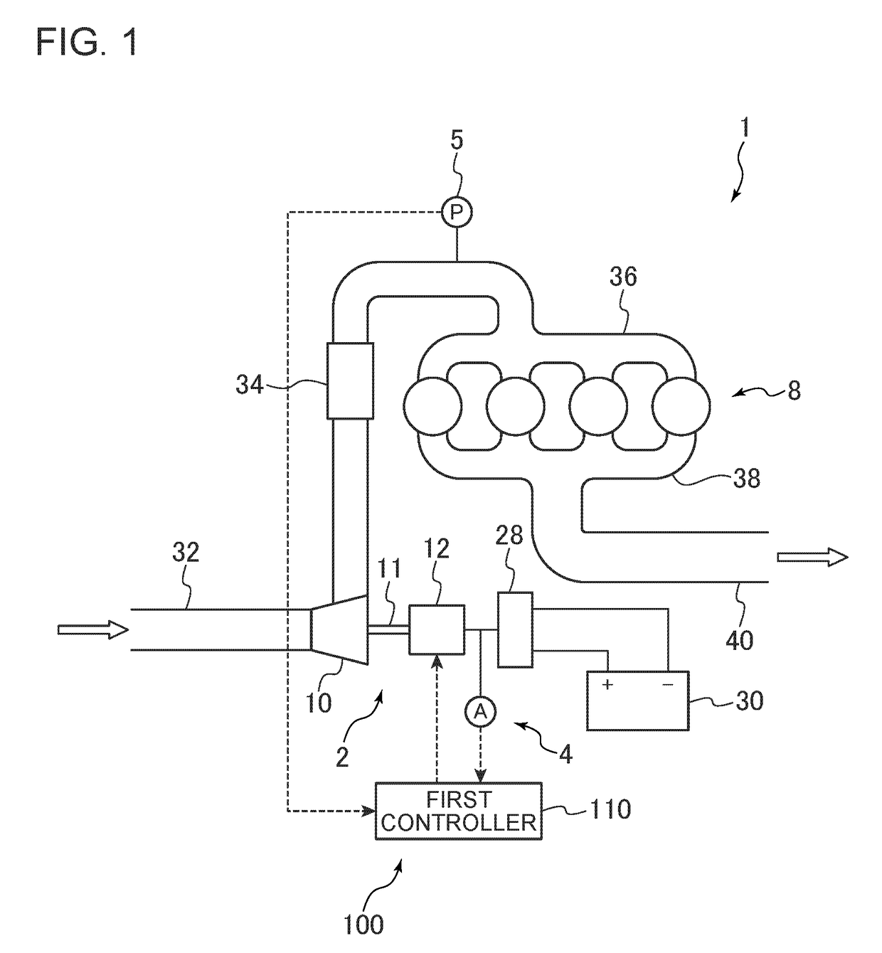
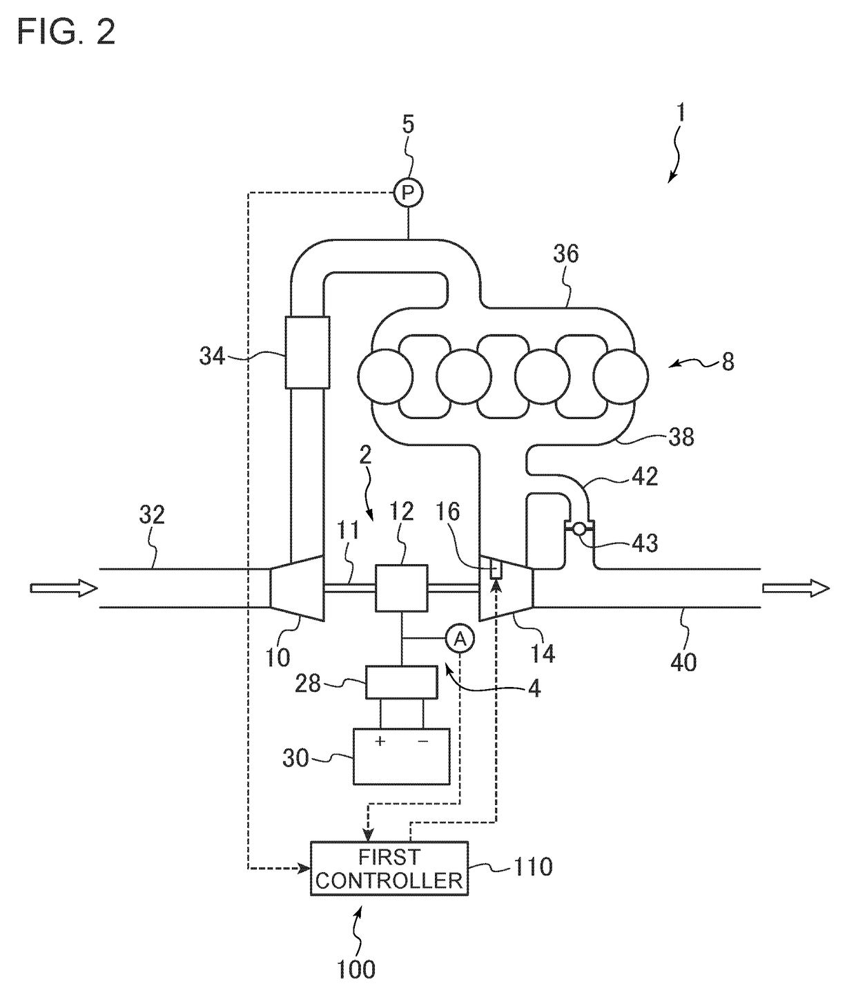
[0052]FIGS. 1, 2, and 9 to 12 are each a configuration diagram of a supercharging system according to an embodiment. As depicted in FIGS. 1, 2, and 9 to 12, the supercharging system 1 includes a first supercharger 2 configured to compress a pressure of air to be supplied to an engine 8 mounted to a vehicle or the like, a leakage current measuring part 4, and a control device 100. The first supercharger 2 includes a first compressor 10 for compressing air to be supplied to the engine 8, and a motor 12 for driving the first compressor 10. The leakage current measuring part 4 is configured to measure a ...


PUM


Abstract

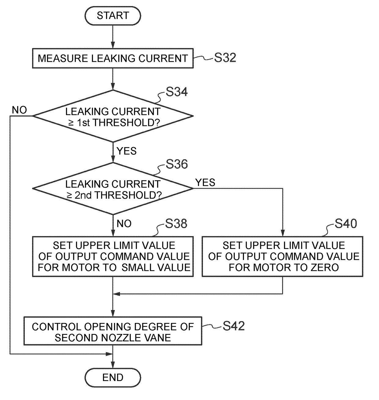
A supercharging system includes: a first supercharger including a first compressor for compressing air to be supplied to an engine and a motor for driving the first compressor; a leakage current measuring part for measuring a leakage current of the motor; and a first controller for controlling the first supercharger. The first controller includes a motor control part configured to, when a measurement result by the leakage current measuring part is not less than a first threshold, set an upper limit value of an output command value for the motor to be lower than when the measurement result is less than the first threshold, and to control an output of the motor within a range which does not exceed the upper limit value.

Description

TECHNICAL FIELD[0001]The present disclosure relates to a supercharging system, a control device for the supercharging system, and a method for operating the supercharging system.BACKGROUND ART[0002]It is known that occurrence of insulation degradation of winding, which is a typical example of malfunction of a motor, causes an increase in a leakage electric current with development of the insulation degradation.[0003]To detect such a leakage current, Patent Document 1 discloses an electric leakage detection system for detecting a presence or absence of electric leakage when an inverter motor is supplied with voltage, provided for a motor compressor system for air conditioning. In this electric leakage detection system, electric leakage is detected by an electric leakage detection sensor. If electric leakage is detected, power supply to the inverter motor is immediately stopped to stop operation of the inverter motor.CITATION LISTPatent Literature[0004]Patent Document 1: JP2000-298220...

Claims


Application Information

Patent Timeline
IPC IPC(8): F02B37/24F02B39/10F02B37/013G01R19/165F02B37/00
CPCF02B37/24F02B39/10F02B37/013F02B37/004G01R19/165F02B37/14Y02T10/12
Inventor YAMASHITA, YUKIOKUBO, HIROYOSHIGOTO, MITSUFUMISAKAMOTO, MUSASHI
Owner MITSUBISHI HEAVY IND LTD
Learn More