Control apparatus for a hybrid vehicle drive system

a control apparatus and hybrid vehicle technology, applied in vehicle position/course/altitude control, process and machine control, instruments, etc., can solve the problems of relatively high deterioration of drivability of hybrid vehicle upon switching of the drive system, and reduced risk of generation of drive mode switching shock. , the effect of smooth and rapid switching

Inactive Publication Date: 2015-12-17
TOYOTA JIDOSHA KK
View PDF1 Cites 4 Cited by
  • Summary
  • Abstract
  • Description
  • Claims
  • Application Information

AI Technical Summary

Benefits of technology

[0016]According to the above-described fifth preferred form of the invention, the first one of the electric motor drive modes is once established when the drive system is required to establish the motor drive mode during the first speed one or the second speed one of the constant-speed-ratio drive modes, and the second one of the electric motor drive modes is once established when the drive system is required to establish the motor drive mode during the third speed one or the fourth speed one of the constant-speed-ratio drive modes. Thus, the first one or the second one of the electric motor drive modes is once established with a releasing action of only one coupling element when the drive system is in the first, second, third or fourth speed one of the constant-speed-ratio drive modes. Accordingly, the drive system can be smoothly and rapidly switched from the first, second, third or fourth speed one of the constant-speed-ratio drive modes in which the hybrid vehicle is driven by the engine operated as a vehicle drive power source in response to a request for the motor drive mode, so that deterioration of drivability of the hybrid vehicle upon switching of the drive system to the desired constant-speed-ratio drive mode can be reduced.

Problems solved by technology

Accordingly, there is a risk of generation of an engaging shock of the coupling element to be brought into the engaged state, namely, a drive mode switching shock of the hybrid vehicle drive system.
In this respect, the risk of generation of the drive mode switching shock is considered to be relatively high.

Method used


Image

  • Control apparatus for a hybrid vehicle drive system
  • Control apparatus for a hybrid vehicle drive system
  • Control apparatus for a hybrid vehicle drive system

Examples


embodiment

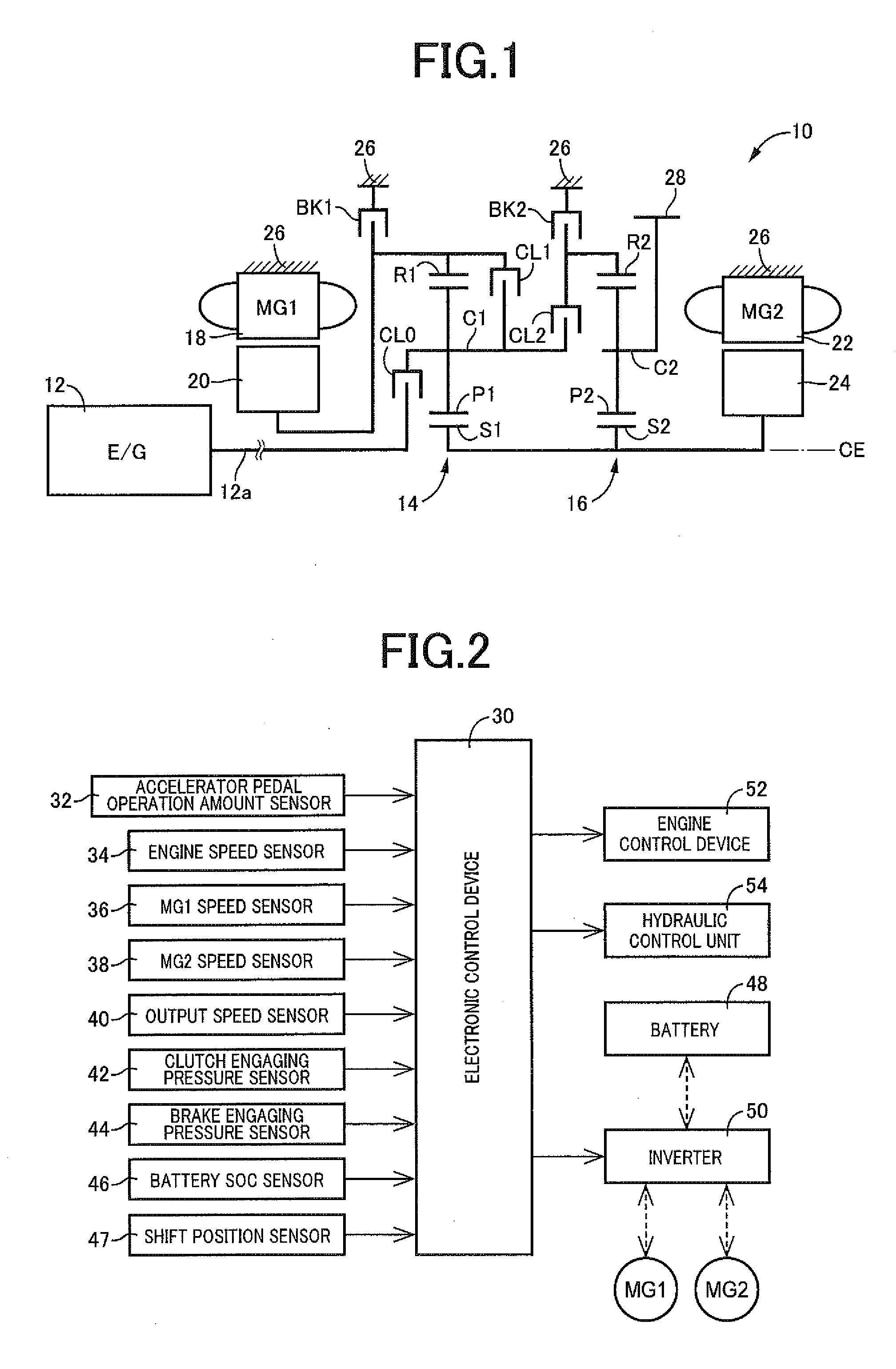
[0033]FIG. 1 is the schematic view showing an arrangement of a hybrid vehicle drive system 10 (hereinafter referred to simply as a “drive system 10”) to which the present invention is suitably applicable. As shown in FIG. 1, the drive system 10 according to the present embodiment is of a transversely installed type suitably used for an FF (front-engine front-drive) type vehicle, and is provided with a main vehicle drive power source in the form of an engine 12, a first electric motor MG1, a second electric motor MG2, a first differential mechanism in the form of a first planetary gear set 14, and a second differential mechanism in the form of a second planetary gear set 16, which are disposed on a common axis CE. In the following description of the embodiment, the direction of extension of this axis CE will be referred to as an “axial direction”. The drive system 10 is constructed substantially symmetrically with respect to the axis CE. In FIG. 1, a lower half of the drive system 10...


PUM


Abstract

Control apparatus for hybrid vehicle drive system including a plurality of coupling elements which selectively connect selected ones of rotary components of differential device and stationary member to each other, and which permit the drive system to be placed in one of electric motor drive mode, and constant-speed-ratio drive modes in which an engine is operated as drive power source, control apparatus selectively establishing one of hybrid drive mode and electric motor drive mode, with an engaging action of one of coupling elements, and one of constant-speed-ratio drive modes, with an engaging action of another coupling element as well as or in place of engaging action of above-indicated one coupling element, control apparatus including drive mode switching portion configured to establish one of hybrid drive mode and electric motor drive mode, when drive system is required to be switched from neutral state to a vehicle drive state.

Description

CROSS REFERENCE TO RELATED APPLICATION[0001]The present application claims the priority from Japanese Patent Application No. 2014-122924 filed on Jun. 13, 2014, the disclosure of which is herein incorporated by reference in its entirety.BACKGROUND OF THE INVENTION[0002]1. Field of The Invention[0003]The present invention relates to an improvement of a control apparatus for a drive system of a hybrid vehicle.[0004]2. Description of Related Art[0005]There is known a hybrid vehicle drive system including: a differential device which comprises a first differential mechanism and a second differential mechanism and which comprises four rotary components; an engine, a first electric motor, a second electric motor and an output rotary member which are respectively connected to the four rotary components; and a plurality of coupling elements which selectively connect selected ones of the rotary components or one of the rotary components and a stationary member to each other, and which permit...

Claims


Application Information

Patent Timeline
Patent Type & Authority Applications(United States)
IPC IPC(8): B60W20/00B60W10/06B60K6/547B60W10/12B60K6/365B60K6/445B60W10/115B60W10/08B60L50/16
CPCB60W20/40Y10S903/919B60W10/06B60W10/08B60W10/12B60K6/365B60K6/445B60K6/547B60W2710/021B60W2710/06B60W2710/08B60W2710/1005B60W2710/12Y10S903/93Y10S903/911B60W10/115B60W30/20B60W2510/244B60W2520/10B60W2540/10B60W2540/16B60W2710/0666B60W2710/083B60W10/101B60W20/10Y02T10/62
Inventor KANAYAMA, TAKESHIBABA, SHINICHI
Owner TOYOTA JIDOSHA KK
Why Eureka
Try Eureka