Vehicle and control method for vehicle

a technology for vehicles and control methods, applied in mechanical equipment, engine-driven generators, transportation and packaging, etc., can solve the problems of engine stop time, increase the likelihood of engine start-up shock, engine deterioration, etc., to improve fuel economy, enhance vehicle efficiency, and improve the effect of fuel economy

Active Publication Date: 2018-10-18
TOYOTA JIDOSHA KK
View PDF1 Cites 3 Cited by
  • Summary
  • Abstract
  • Description
  • Claims
  • Application Information

AI Technical Summary

Benefits of technology

[0004]By the way, the time in which the engine is stopped from being operated (referred to also as an engine stop time) can be lengthened as an engine start-up threshold for determining that the battery SOC value has fallen to such an extent that the engine needs to be started up to charge the battery falls. Therefore, a contribution is considered to be made to an improvement in fuel economy (referred to also as the enhancement of vehicle efficiency). On the other hand, as the engine start-up threshold falls, the likelihood of the occurrence of a shock resulting from start-up of the engine increases due to a deficiency in output electric power of the battery ascribable to a fall in the battery SOC value, or the rise in the engine rotational speed is delayed in the process of starting up the engine (i.e., the time that is needed to start up the engine lengthens), so a deterioration in drivability may be caused. Meanwhile, it is possible to conceive a vehicle in which first operation control for causing the vehicle to run based on a driver's driving operation and second operation control for causing the vehicle to run by automatically setting a target running state based on at least one of map information and road information and automatically carrying out acceleration / deceleration based on the target running state can be selectively performed. In this vehicle, at the time of the second operation control, the frequency with which a demand for sudden acceleration arises is low, and the number of scenes in which the engine is started up with large running power of the vehicle is considered to be smaller than at the time of the first operation control. Besides, at the time of the second operation control, it is also possible to assume that a deterioration in drivability is not recognized by the driver even when the driving force is reduced in starting up the engine. Therefore, it is desirable to improve fuel economy by setting the engine start-up threshold in consideration of the difference in operation control, instead of adopting an aspect in which the engine start-up threshold is uniformly set regardless of the difference in operation control.

Problems solved by technology

On the other hand, as the engine start-up threshold falls, the likelihood of the occurrence of a shock resulting from start-up of the engine increases due to a deficiency in output electric power of the battery ascribable to a fall in the battery SOC value, or the rise in the engine rotational speed is delayed in the process of starting up the engine (i.e., the time that is needed to start up the engine lengthens), so a deterioration in drivability may be caused.
Therefore, the engine stop time can be made long at the time of the second operation control when a deterioration in drivability resulting from a delay in the rise of the engine rotational speed in the process of starting up the engine is considered to be more difficult for the driver to recognize than at the time of the first operation control.

Method used


Image

  • Vehicle and control method for vehicle
  • Vehicle and control method for vehicle
  • Vehicle and control method for vehicle

Examples


first embodiment

[0080]In the present embodiment of the disclosure, a relationship in magnitude of the engine start-up threshold Sengst among the respective types of operation control of the vehicle 10, which is different from that of the foregoing first embodiment of the disclosure, is exemplified.

[0081]In automatic operation control, a deterioration in drivability resulting from a delay in the rise of the engine rotational speed Ne in the process of starting up the engine is considered to be more difficult to recognize than in manual operation control.

[0082]Therefore, this automatic operation control gives priority to an improvement in fuel economy. The start-up threshold setting unit 99 sets each of the engine start-up threshold Sengst1 (at the time of unmanned running) and the engine start-up threshold Sengst2 (at the time of automatic manned running) smaller than both the engine start-up threshold Sengst3 (at the time of cruising) and the engine start-up threshold Sengst4 (at the time of normal...

third embodiment

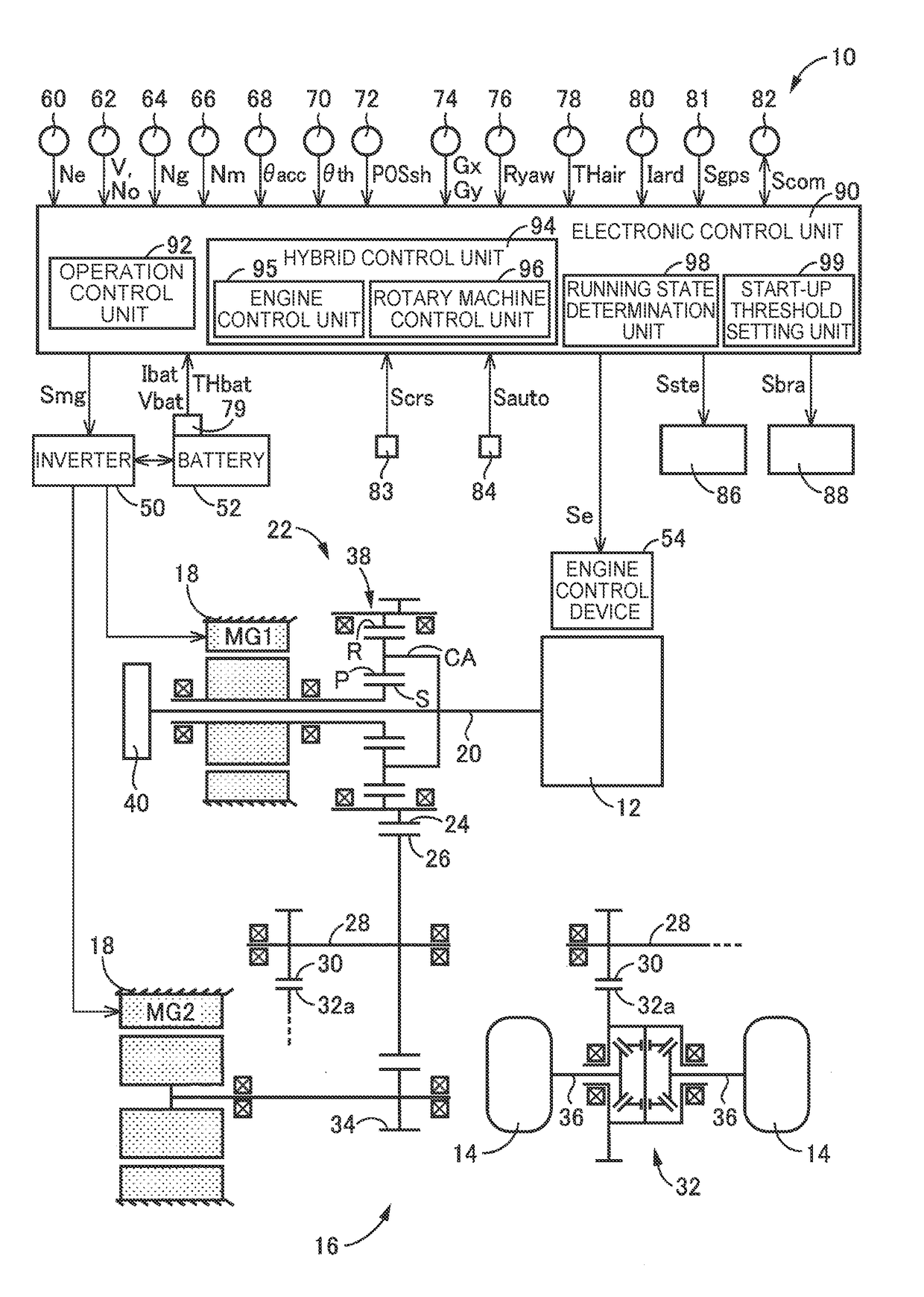
[0095]Besides, in the foregoing third embodiment of the disclosure, the vehicle 100 may be a vehicle that is not equipped with the clutch K0 and that has the engine 102 and rotary machine MG directly coupled to the input side of the torque converter 108. In short, the disclosure is applicable to any vehicle that is equipped with an engine, a rotary machine capable of generating a driving torque, and a battery that is charged by a motive power of the engine and that supplies an electric power to the rotary machine. Incidentally, in the vehicle 100, the torque converter 108 is used as a hydraulic transmission device. However, another hydraulic transmission device such as a fluid coupling with no torque amplification effect or the like may be used. Besides, the torque converter 108 may not necessarily be provided, or may be replaced with a simple clutch.

[0096]Besides, in each of the foregoing embodiments of the disclosure, the vehicle 10 or 100 is exemplified as the vehicle to which th...


PUM


Abstract

An electronic control unit is configured to make an engine start-up threshold at a time of second operation control smaller than an engine start-up threshold at a time of first operation control. Therefore, the engine stop time at the time of the first operation control can be made long. In consequence, the vehicle efficiency can be enhanced in a vehicle in which the first operation control and the second operation control can be selectively performed.

Description

INCORPORATION BY REFERENCE[0001]The disclosure of Japanese Patent Application No. 2017-082408 filed on Apr. 18, 2017 including the specification, drawings and abstract is incorporated herein by reference in its entirety.BACKGROUND1. Technical Field[0002]The disclosure relates to a vehicle that includes an engine, a rotary machine, and a battery, and a control method for the vehicle.2. Description of Related Art[0003]A control apparatus for a vehicle that is equipped with an engine, a rotary machine that can generate a driving torque, and a battery that is charged by a motive power of the engine and that supplies an electric power to the rotary machine is well known. For instance, a vehicular running control apparatus described in Japanese Patent Application Publication No. 2012-86771 (JP 2012-86771 A) is such an example. It is disclosed in this Japanese Patent Application Publication No. 2012-86771 (JP 2012-86771 A) that the engine is prevented from being frequently started up and s...

Claims


Application Information

Patent Timeline
Patent Type & Authority Applications(United States)
IPC IPC(8): B60W20/13B60W10/06B60W10/08B60W20/12B60W30/14B60W30/16B60L50/16
CPCB60W20/13B60W10/06B60W10/08B60W20/12B60W30/143B60W30/16B60W2510/244B60W2550/14B60W2510/0638B60W2510/083B60W2710/0644B60W2710/083B60W2720/106B60W2750/308Y10S903/93B60W20/40B60W2520/105B60K6/445B60W20/11B60W10/26B60K2006/4825Y02T10/40Y02T10/62B60W2552/00B60W2754/30
Inventor KOHNO, TAKASHIKUMAZAKI, KENTA
Owner TOYOTA JIDOSHA KK
Why Eureka
Try Eureka