Randomly bendable and shapable LED light bar

a led light bar and random bend technology, applied in the field of decorative lighting, can solve the problems of inconvenient installation and setting of smd-type flexible light bars, inability to bend and bend freely, and the application of smd-type flexible pcb light bars above is greatly limited, so as to achieve better fixed effect and better insulation

Active Publication Date: 2017-11-16
YANG YI +2
View PDF0 Cites 19 Cited by
  • Summary
  • Abstract
  • Description
  • Claims
  • Application Information

AI Technical Summary

Benefits of technology

[0012]As the longitudinal groove for accommodating the LED light strings is formed in the inner wrapping layer, the manufacturing difficulty of the longitudinal groove is lower than that of modes such as injection molding wrapping. As the inner wrapping layer is wrapped by the outer wrapping layer, the situation that the LED light strings get loose from the longitudinal groove can be avoided.
[0013]Further, the LED light emitting units, and the welded / soldered parts between the LED light emitting units and the fine wires are coated with epoxy resin, which can achieve a better fixed effect and a better insulation.

Problems solved by technology

For example, it is likely to be broken and further make the LED chips 14 desoldering while it is twisted and bent randomly, due to the limited flexibility of the flexible PCBs 13.
In addition, it is inconvenient to install and set the SMD-type flexible light bar, whose installation and set depend on the exterior buckles and grooves.
All in all, the SMD flexible PCB light bar above is greatly limited in its application.
As the longitudinal groove for accommodating the LED light strings is formed in the inner wrapping layer, the manufacturing difficulty of the longitudinal groove is lower than that of modes such as injection molding wrapping.

Method used


Image

  • Randomly bendable and shapable LED light bar
  • Randomly bendable and shapable LED light bar
  • Randomly bendable and shapable LED light bar

Examples


embodiment 1

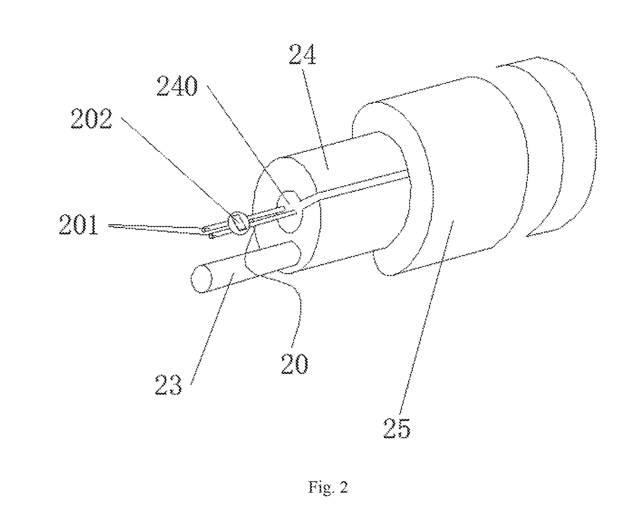
[0028]FIG. 2 shows the section view of the embodiment 1 and the electrical schematic diagram of the embodiment 1 is shown in FIG. 3, wherein the dots refer to the welding points.

[0029]The randomly bendable and shapeable LED light bar disclosed by the embodiment 1 comprises LED light strings 20, a shaping metal rod 23 and an insulating wrapping layer, wherein each LED light string comprises two fine wires 201 in parallel and a plurality of LED light emitting units 202; the anode and the cathode of each LED light emitting unit 202 are respectively welded / soldered and fixed with the two fine wires 201; the two fine wires 201 are respectively electrically connected with the anode and the cathode of a power supply; the plurality of LED light emitting units 202 are connected in parallel; the LED light strings 20 are parallel to the shaping metal rod 23 and are both wrapped by the insulating wrapping layer.

[0030]The fine wires 201 of the LED light strings 20 are enameled wires with good in...

embodiment 2

[0035]FIG. 4 is the profile view of the embodiment 2, FIG. 5 is the sectional view of A-A of FIG. 4, FIG. 6 is the electric schematic diagram of the embodiment 2, and the dots in FIG. 6 are welding points.

[0036]The randomly bendable and shapeable LED light bar disclosed by the embodiment 2 is of the generally same structure as that of the randomly bendable and shapeable LED light bar disclosed by the embodiment 1, and the differences are that the randomly bendable and shapeable LED light bar disclosed by the embodiment 2 further comprises an anode power supply wire 21 and a cathode power supply wire 22 which are electrically connected with the anode and the cathode of the power supply respectively. The anode power supply wire 21 and the cathode power supply wire 22 are insulated with respect to each other. One end of a fine wire 201 is electrically connected with the anode power supply wire 21, and one end of another fine wire 201 is electrically connected with the cathode power sup...

embodiment 3

[0041]The randomly bendable and shapeable LED light bar disclosed by the embodiment 3 is of the generally same structure as that of the randomly bendable and shapeable LED light bar disclosed by the embodiment 2, and the difference is that the embodiment 3 further comprises two LED light strings, that is, an LED light string 20 and an LED light string 20′.

[0042]Please refer to FIG. 7 which is the electric schematic diagram of the embodiment 3, and the dots in Fig. are welding points.

[0043]The LED light string 20 is parallel to the LED light string 20′. Multiple LED light emitting units 202 of the LED light string 20 and multiple LED light emitting units 202′ of the LED light string 20′ are distributed at intervals. The LED light emitting units 202 and the LED light emitting units 202′ can be SMD LED of different light emitting colors, so as to achieve a colorful light emitting effect.

[0044]The two fine wires 201 of the LED light string 20 are connected and fixed with epoxy resin 203...


PUM


Abstract

A randomly bendable and shapeable LED light bar is provided, including a plurality of LED light strings in parallel, a shaping metal rod and an insulating wrapping layer, wherein each LED light string includes two fine leads in parallel and a plurality of LED light emitting units; an anode and a cathode of each LED light emitting unit are welded/soldered with the two fine leads; the two fine leads are electrically connected with an anode and a cathode of a power supply; the plurality of LED light strings are parallel to the shaping metal rod and are both wrapped by the insulating wrapping layer. Compared with the prior art, the randomly bendable and shapeable LED light bar disclosed is relatively flexible, can be formed into various rich shapes, and is convenient to mount and shape, reliable in light emission, relatively high in practicability and relatively wide in application range.

Description

CROSS-REFERENCE TO RELATED APPLICATION[0001]This application claims priority to CN 201620437517.1, having a filing date of May 12, 2016, the entire contents of which are hereby incorporated by reference.FIELD OF TECHNOLOGY[0002]The following relates to the field of decorative lighting, and in particular to an LED light bar.BACKGROUND[0003]LED lamps are characterized by their energy conservation, environment protection, soft and even light, various hues and the like, and win great popularity among customers. Recent developments in LEDs permit them to be available in various forms and be widely used in holiday decoration, home decoration, city lighting project and various entertainment places.[0004]The existing LED light bars are mostly manufactured by using flexible PCBs. For example, the patent CN 201520243185.9 discloses a SMD flexible PCB light bar, and FIG. 1 shows the part sectioned view of the SMD-type flexible PCB light bar of the related art. The SMD-type flexible light bar c...

Claims


Application Information

Patent Timeline
Patent Type & Authority Applications(United States)
IPC IPC(8): F21S4/26H01L33/48H01L27/15H01L33/62H01L33/56F21W121/00
CPCF21S4/26H01L33/62H01L33/486H01L27/156H01L33/56F21W2121/00F21Y2115/10H01L25/0753
Inventor YANG, YIYU, QINGQIANG
Owner YANG YI
Why Eureka
Try Eureka