Heat dissipation structure and illumination device

Inactive Publication Date: 2017-11-16
HONGO TAKENOBU +1
View PDF10 Cites 1 Cited by
  • Summary
  • Abstract
  • Description
  • Claims
  • Application Information

AI Technical Summary

Benefits of technology

The invention is a heat dissipating structure for LED lights that is efficient and easy to implement. The design allows for the heat from the LED chips to be efficiently spread through the layers of graphite, but it is ultimately released through metal layers or heat dissipating fins. This means that the space occupied by the heat dissipation structure is not reduced. Overall, the invention allows for a simplified and efficient way to dissipate heat, making it suitable for use in LED lights.

Problems solved by technology

However, since the conventional heat dissipation structure illustrated in Patent Literature 1 above is provided with a number of heat dissipating fins made of a metal so as to be in contact with air, the heat dissipation structure disadvantageously occupied too much space.
In some cases, this prevented the device to be provided with the heat dissipation structure from being made compact.
In such an illumination device, it was difficult for the conventional heat dissipation structure to be provided with sufficient heat dissipating property and reduced in weight at the same time.
Furthermore, a housing or the like also used as the heat dissipation structure in order to implement compactness caused the structure to become complicated in conjunction with degradation in heat dissipation efficiency and an increase in manufacturing costs.
However, since the heat was finally released, for example, through the metal layers or the heat dissipating fins, the heat dissipation efficiency was not so high.

Method used


Image

  • Heat dissipation structure and illumination device
  • Heat dissipation structure and illumination device
  • Heat dissipation structure and illumination device

Examples


Embodiment Construction

[0035]Now, with reference to the accompanying drawings, an embodiment of the present invention will be described. Note that for ease of understanding, each of the figures below may include those parts that are not illustrated or are illustrated in a simplified manner, and respective parts are not always drawn to scale.

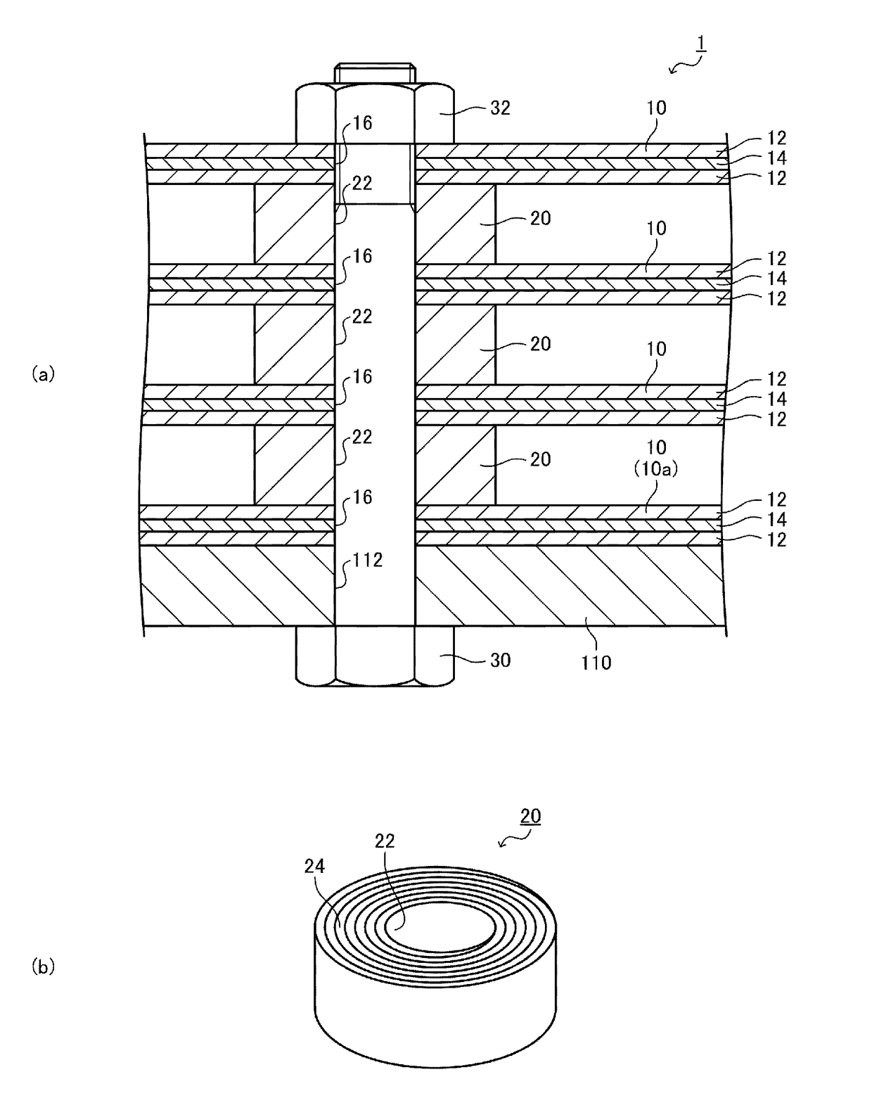
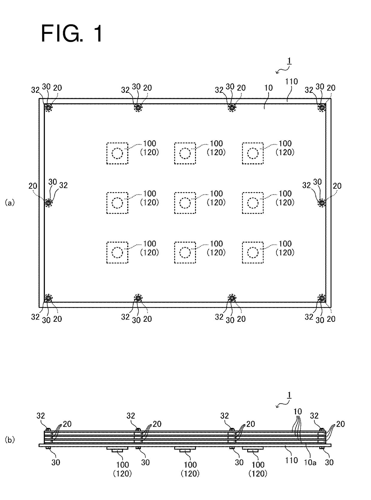
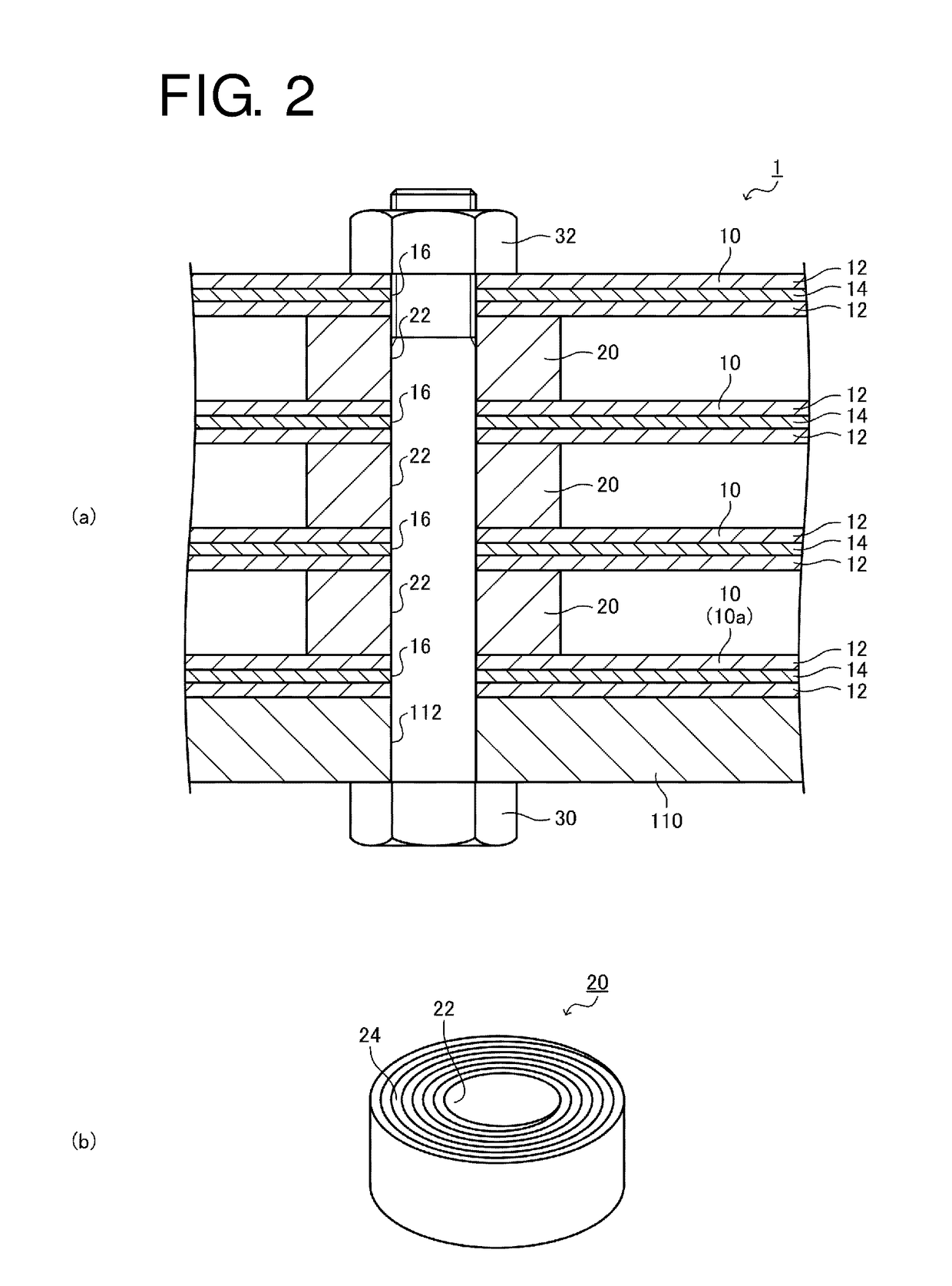
[0036]First, a description will be given of a heat dissipation structure 1 according to this embodiment. FIG. 1(a) is a schematic plan view illustrating the heat dissipation structure 1 according to this embodiment, and FIG. 1(b) is a schematic front view illustrating the heat dissipation structure 1. In addition, FIG. 2(a) is an enlarged schematic cross-sectional view illustrating part of the heat dissipation structure 1, and FIG. 2(b) is a schematic perspective view illustrating connection members 20. The heat dissipation structure 1 is to release heat emitted from heat sources 100, and as illustrated in the figures, provided with a plurality of heat reception / dissip...


PUM

PropertyMeasurementUnit
Distanceaaaaaaaaaa
Heataaaaaaaaaa
Brightnessaaaaaaaaaa

Abstract

Provided is a heat dissipation structure and an illumination device which are capable of dissipating heat readily and efficiently. A heat dissipation structure 1 configured to release heat from a heat source 100 is provided with a plurality of heat reception / dissipation members 10 which have expanded graphite layers containing expanded graphite and which are spaced apart from each other; and a connection member 20 configured to connect the heat reception / dissipation members 10 together. The heat reception / dissipation members 10 each have the expanded graphite layer as the outermost layer and are disposed such that the expanded graphite layers face each other.

Description

CROSS-REFERENCE TO RELATED APPLICATIONS[0001]This application is a national phase filing under 35 USC §371 of International Application No. PCT / JP2015 / 081652, filed Nov. 10, 2015, and which claims priority to Japanese Patent Application No. 2014-229848, filed on Nov. 12, 2014, the contents of which are incorporated herein by reference.STATEMENT REGARDING PRIOR DISCLOSURE BY THE INVENTOR OR A JOINT INVENTOR UNDER 37 CFR 1.77(B) (6)[0002]A device corresponding to the invention claimed in this application and made by Takenobu Hongo was sold or offered for sale by Applicant on the following dates: Aug. 8, 2014; Aug. 20, 2014; Aug. 25, 2014; Sep. 2, 2014; Sep. 12, 2014; Sep. 17, 2014; Sep. 22, 2014; Oct. 20, 2014; and Oct. 24, 2014. The device was also exhibited to the public by Applicant on the following dates: Sep. 15, 2014; and Sep. 30, 2014. The effective filing date of this application is Nov. 12, 2014. The details of the sales and exhibitions were described in a document filed at t...

Claims


Application Information

Patent Timeline
IPC IPC(8): F21V29/507F21K9/233H05B33/08B32B27/08C01B32/20H05B44/00
CPCF21V29/507H05B33/0848F21K9/233C01B32/20B32B2307/302B32B27/08B32B2307/202F21Y2115/10H01L2924/0002H01L23/3672H01L23/373H01L23/4006C01B32/225F21V23/007F21V23/0464F21W2131/103F21V29/70F21V29/763F21V29/767F21V29/83F21Y2105/16B32B9/041B32B2250/03B32B2250/40B32B9/007B32B2457/00B32B15/20B32B2250/24B32B2250/05B32B27/32B32B7/02B32B27/18B32B2264/102B32B2439/40B32B5/024B32B5/028B32B7/12B32B5/26B32B2250/20B32B2250/02B32B2307/724B32B27/12B32B29/02B32B27/36B32B2262/0253B32B2262/0276B32B2307/72B32B2419/00H01L2924/00H05B45/14
Inventor HONGO, TAKENOBU
Owner HONGO TAKENOBU
Why Eureka
Try Eureka