Capacitor Module

Inactive Publication Date: 2017-11-16
DENSO CORP
View PDF6 Cites 0 Cited by
  • Summary
  • Abstract
  • Description
  • Claims
  • Application Information

AI Technical Summary

Benefits of technology

[0056]Next, advantageous effects of this embodiment are explained. The capacitors 5a and 5b of the capacitor module 1 are the same in capacitance and inner current path structure. Accordingly, by disposing the capacitors 5a and 5b such that the main current directions Ia and Ib are opposite in direction to each other, the parasitic inductance can be reduced effectively.
[0057]The positive conductor part 2 and the negative conductor part 3 are disposed on the opposite surfaces of the insulating substrate 41. Accordingly, it is possible to dispose the positive conductor part 2 and the negative conductor part 3 such that they overlap in the Z direction. Therefore, it is possible that a current flowing through the current path including the capacitor 5a and a current flowing through the current pa

Problems solved by technology

When the switching elements switch on and off to intermit a current, there occurs a surge voltage due to a parasitic inductance of the power conversion apparatus.
However, a parasitic inductance caused by a current flowing through the capacitor cannot be reduced sufficiently by only contriving the layout of the conductors of the power conversion apparatus.
However, in this electronic component mounting structure, if the e

Method used


Image

  • Capacitor Module
  • Capacitor Module
  • Capacitor Module

Examples


Example

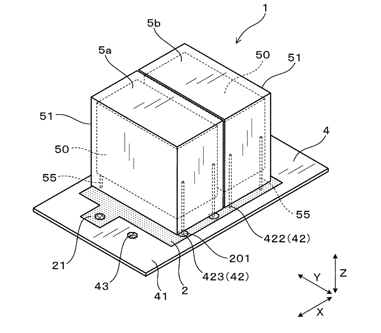
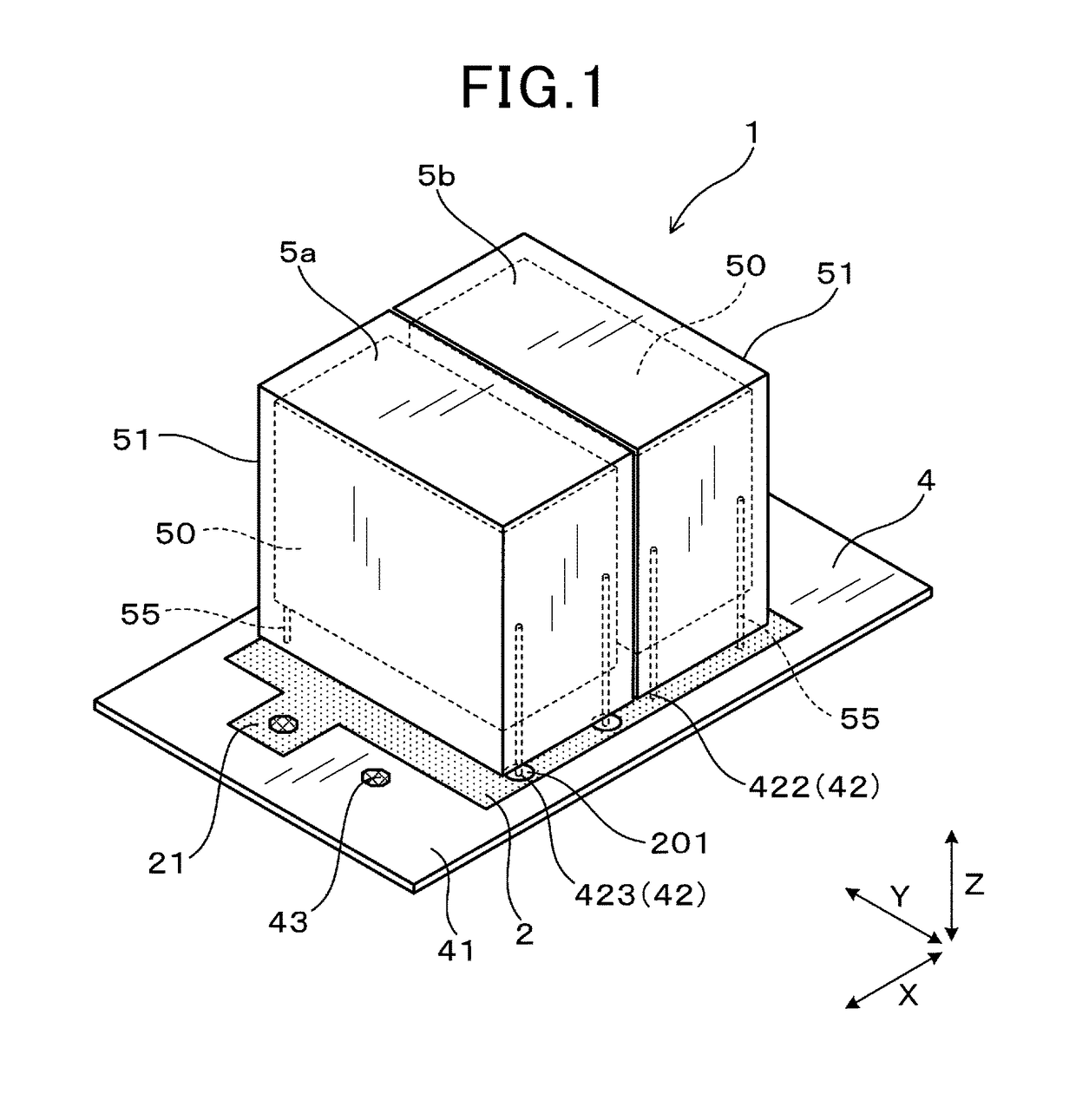
[0033]A capacitor module 1 according to a first embodiment of the invention is described with reference to FIGS. 1 to 10. As shown in FIGS. 1 to 4, the capacitor module 1 includes a circuit board 4 having a positive conductor part 2 and a negative conductor part 3, and capacitors 5a and 5b mounted on the circuit board 4.

[0034]The capacitors 5a and 5b are the same as each other in capacitance and in structure of internal current path. As shown in FIGS. 5 and 6, the capacitors 5a and 5b are arranged adjacent to each other so as to align to a direction perpendicular to main current directions Ia and Ib of their internal current paths. The capacitors 5a and 5b are connected to the positive conductor part 2 and negative conductor part 3 such that the main current directions Ia and Ib are opposite to each other.

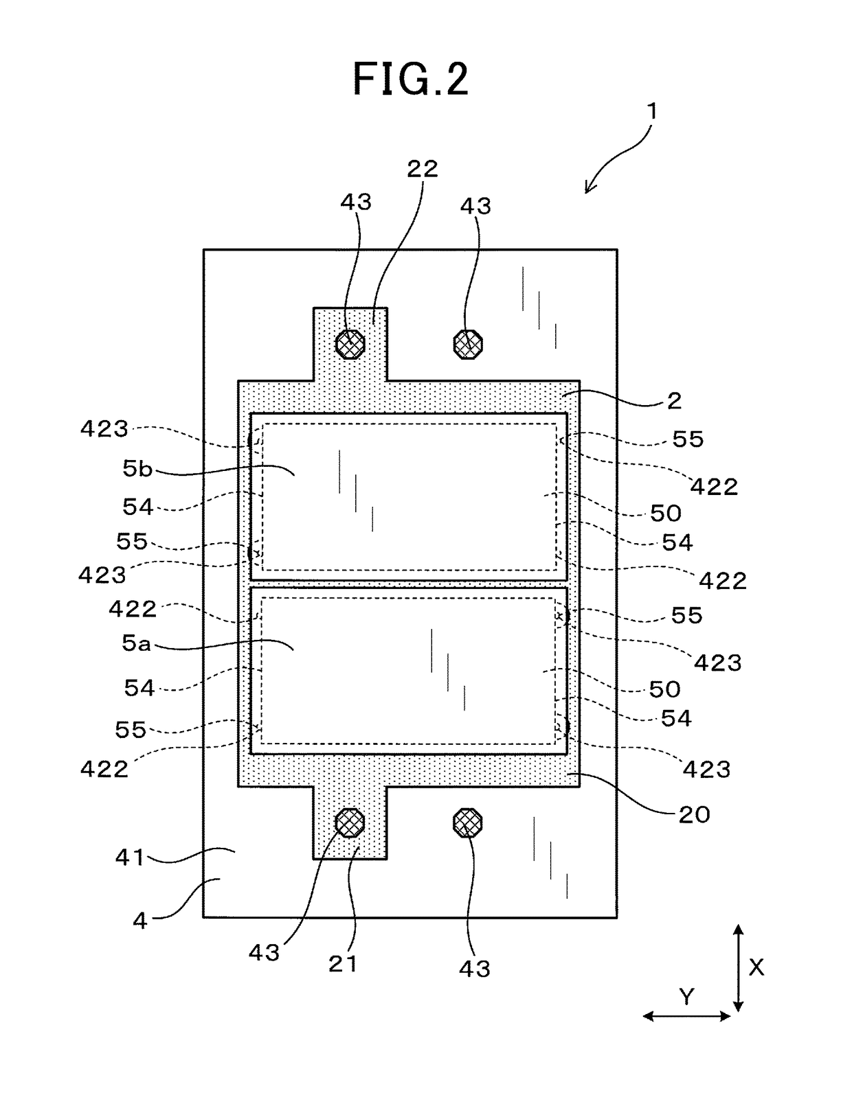
[0035]In the following, the arranging direction of the capacitors 5a and 5b may be referred to as an X direction, the normal direction of the circuit board 4 may be referred to as ...

Example

Comparative Example 1

[0059]As shown in FIGS. 11 and 12, in a capacitor module 9 as comparative example 1, the capacitors 5a and 5b are wired such that their main current directions Ia and Ib are the same as each other. The capacitor module 9 has a circuit board 94 which is different in structure from the circuit board 4 of the first embodiment. The circuit board 94 is formed with the positive and negative through holes 422 and 423 which are different in arrangement from those of the circuit board 4 of the first embodiment. In comparative example 1, the positions of the lead parts 55 of the capacitors 5a and 5b connected to the positive conductor part 2 are on the same side in the Y direction. Except for the above, comparative example 1 is the same in structure as the first embodiment. Accordingly, in comparative example 1, since the main current directions Ia and Ib of the capacitors 5a and 5b are the same as each other, the magnet fluxes due to currents flowing through the capacito...

Example

Comparative Example 2

[0060]Comparative example 2 is an example of a capacitor module 90 in which the two capacitors 5a and 5b are different from each other in size and capacitance as shown in FIG. 13. In this example, even if main current directions Id and Ie of currents flowing through the capacitors 5a and 5b are opposite to each other, since the magnitudes of magnetic fluxes due to the currents are different from each other, the parasitic inductance cannot be reduced sufficiently.


PUM

PropertyMeasurementUnit
Currentaaaaaaaaaa
Distanceaaaaaaaaaa
Capacitanceaaaaaaaaaa

Abstract

A capacitor module includes a circuit board including a positive conductor part and a negative conductor part, and capacitors mounted on the circuit board. The capacitors have the same capacitance and the same inner current path structure. The capacitors are arranged in a direction perpendicular to main current directions of the inner current path structures of the capacitors. Each adjacent two of the capacitors are connected to the positive conductor part and the negative conductor part such that the main current directions thereof are opposite in direction to each other.

Description

[0001]This application claims priority to Japanese Patent Applications No. 2016-95921 filed on May 12, 2016, and No. 2017-63421 filed on Mar. 28, 2017, the entire contents of which are hereby incorporated by reference.BACKGROUND OF THE INVENTION1. Field of the Invention[0002]The present invention relates to a capacitor module including a plurality of capacitors.2. Description of Related Art[0003]Generally, a power conversion apparatus is provided with a capacitor for smoothing a voltage supplied from a DC power source to a switching circuit section including switching elements thereof. When the switching elements switch on and off to intermit a current, there occurs a surge voltage due to a parasitic inductance of the power conversion apparatus. It is known to reduce such parasitic inductance by carefully choosing the layout of conductors of the power conversion apparatus.[0004]However, a parasitic inductance caused by a current flowing through the capacitor cannot be reduced suffic...

Claims


Application Information

Patent Timeline
IPC IPC(8): H01G4/38H01G4/12H01G4/012H01G4/33H05K1/18
CPCH01G4/38H05K1/181H01G4/33H01G4/012H01G4/12H05K2201/10015H01G2/06H01G4/228H05K1/165H05K1/18H05K2201/09309H05K2201/09672
Inventor MASUZAWA, TAKASHISUZUKI, KEISUKE
Owner DENSO CORP
Why Eureka
Try Eureka