BEST MODE
[0060]Hereinafter, an artificial knee joint capable of preventing dislocation of a thighbone coupling member according to the present invention will be described in detail with reference to the accompanying drawings. Unless otherwise defined, all technical terms used herein have the same meaning as commonly understood by one of ordinary skill in the art to which this invention belongs, but if the meaning of the terms used herein is not consistent with the meaning commonly used, it will be interpreted according to the definition used in the specification. Further, in the following description of the invention, if the related known functions or specific instructions on configuring the gist of the present invention unnecessarily obscure the gist of the invention, the detailed description thereof will be omitted.
[0061]Throughout the specification, when a unit is referred to as “comprising” or “including” at least one component, it does not exclude other components unless stated otherwise and shall be referred to as comprising or including the other components.
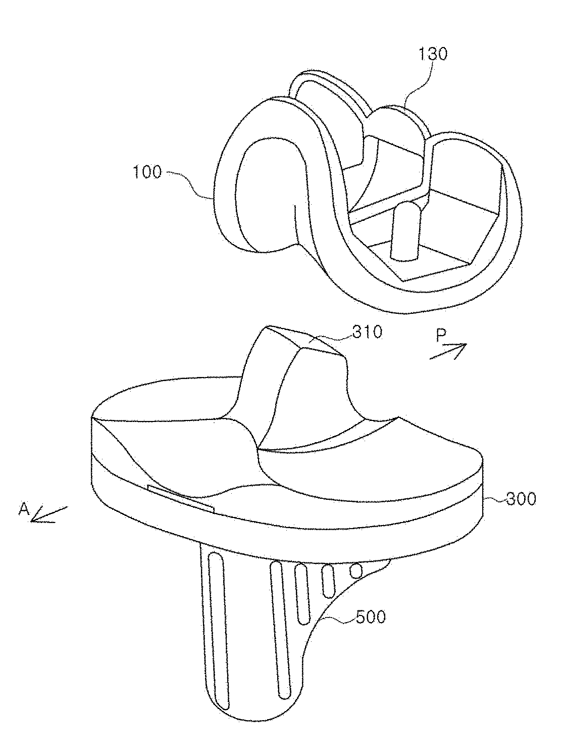
[0062]An artificial knee joint capable of preventing dislocation of a thighbone coupling member according to an embodiment of the present invention will be described in detail with reference to FIGS. 3 to 6.
[0063]As shown in FIG. 3, the artificial knee joint capable of preventing dislocation of a thighbone coupling member includes: a thighbone coupling member 100 coupled to a distal end of the femur; a bearing member 300 disposed between the thighbone coupling member and a tibia coupling member; and a tibia coupling member 500 coupled to a proximal end of the tibia.
[0064]The thighbone coupling member 100 is configured such that a lower end thereof comes into contact with an upper end of the bearing member 300, and moves along with the bearing member during knee movement, wherein the thighbone coupling member includes a cam 130 that comes into direct contact with the bearing member 300.
[0065]The cam 130 is provided at a lower end of the thighbone coupling member 100, and serves to allow smooth rotations of thighbone coupling member 100 and to prevent dislocation by being engaged with a post 310 of the bearing member 300.
[0066]The bearing member 300 is disposed between the thighbone coupling member 100 and the tibia coupling member 500, and includes a post 310 functioning as an alternative to the posterior cruciate ligament.
[0067]As shown in FIGS. 4 to 6, the post 310 is a protruding part from an upper portion of the bearing member 300, and allows the cam 130 to be rotated by being engaged with the post 310 in movement of the thighbone coupling member 100, thereby functioning as an alternative to the posterior cruciate ligament, wherein the post includes: the an upper surface 311 disposed at an upper portion of the post; an upper curved surface 312 disposed right under the upper surface 311; an anterior surface 313 disposed anteriorly to the bearing member 300; an inflection point 314 disposed at a lower end of the upper curved surface 312; and a lower curved surface 315 disposed right under the inflection point 314.
[0068]The upper surface 311 is a surface that is disposed at an upper portion of the post 310, is formed to be inclined, but not be horizontal in the conventional artificial knee joint, and is configured such that a height thereof is gradually reduced as approaching the post 10 from anterior to posterior, whereby as shown in FIG. 6 (c), even if the cam 130 is temporarily dislocated due to excessive rotation of the thighbone coupling member 100, the upper surface guides the cam 130 to descend along the upper surface 311 to be restored from a dislocation state to a normal state, and thus it is possible to improve the life and stability of an artificial knee joint.
[0069]The upper curved surface 312 is a curved surface having the inflection point 314 as its lower end by extending posteriorly from the upper surface 311, and a radius of curvature R1 of the upper curved surface 312 is smaller than a radius of curvature R2 of the lower curved surface 315, whereby as shown in FIG. 6 (b), even if the thighbone coupling member 100 is bent posteriorly and the cam 130 being moved at the lower curved surface 315 is moved up, the cam is stopped by the inflection point 314, thereby having a structure that firstly prevents dislocation from the bearing member 300.
[0070]Further, even if the thighbone coupling member 100 is further bent and the cam 130 is temporarily dislocated, as in the description of the upper surface 311, the cam 130 is guided to descend along the upper surface 311 to be restored from a dislocation state to a normal state, thereby secondly preventing dislocation of the thighbone coupling member.
[0071]The anterior surface 313 is a part that extends anteriorly from the upper surface 311, is connected to an anterior portion of the bearing member 300, and may be formed with a gently curved surface.
[0072]The inflection point 314 is a point at which the curvature changes between the upper curved surface 312 and the lower curved surface 315, and based on the inflection point, the radius of curvature R1 of the upper curved surface 312 is smaller than the radius of curvature R2 of the lower curved surface 315, such that the curvature changes dramatically, whereby as shown in FIG. 6(b), it is possible to efficiently prevent the cam 130 from being dislocated from the post 310.
[0073]The lower curved surface 315 is a curved surface extending downward from the inflection point 314 to a posterior direction, and is configured such that even if the thighbone coupling member 100 is bent posteriorly, the cam 130 is moved along the lower curved surface 315, thereby facilitating smooth rotations. As shown in FIG. 5, the lower curved surface 315 is configured such that a center C1 of curvature of the upper curved surface is disposed anteriorly based on the inflection point 314, and a center C2 of curvature of the lower curved surface is disposed posteriorly based on the inflection point 314, whereby a movement radius of the cam 130 is within the range of the lower curved surface 315, and is stopped by the inflection point 314 when the thighbone coupling member 100 is bent posteriorly, thereby having a structure that prevents dislocation of the thighbone coupling member 100.
[0074]The tibia coupling member 500 is a part that is disposed at the lower portion of the bearing member 300, and is configured such that an upper portion thereof allows the bearing member 300 to be seated thereon, and a lower portion thereof serves to fix the tibia by being coupled thereto, wherein the tibia coupling member 500 is roughly divided into a cemented type to improve bonding strength with tibia and a cementless type without bone cement, and it may have various structures for bonding with other tibia and for internal fixation.
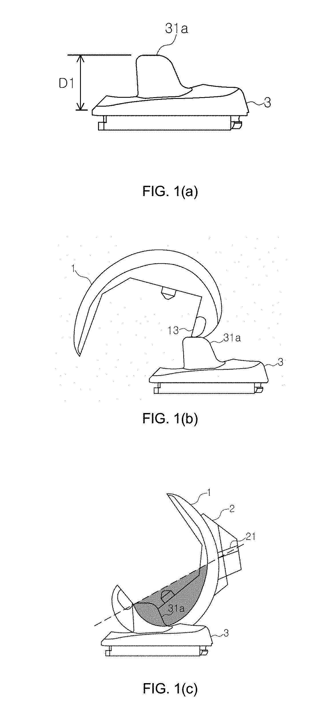
[0075]Hereinbelow, the present invention is compared with the conventional artificial knee joint, and the case of increasing the height of the post in the conventional artificial knee joint, respectively, and a dislocation problem occurring when the thighbone coupling member is bent posteriorly, and the amount of bone required to be cut in knee replacement surgery will be described in detail with reference to FIGS. 1 to 8.
[0076]In the case of the conventional artificial knee joint, as shown in FIG. 1(a), a post 31a is configured such that an upper surface is not inclined, and a posterior vertical surface is formed to be linear, so a jump distance D1 is low, whereby as shown in FIG. 1(b), it has a structure, in which it is difficult to prevent dislocation of the thighbone coupling member 1, and since the upper surface of the post 31b is in a horizontal plane, it is difficult for the thighbone coupling member to be restored to a normal state after it is dislocated. In FIG. 1(c), a dark shaded area below a dotted line indicates the amount of bone to be cut in knee replacement surgery.
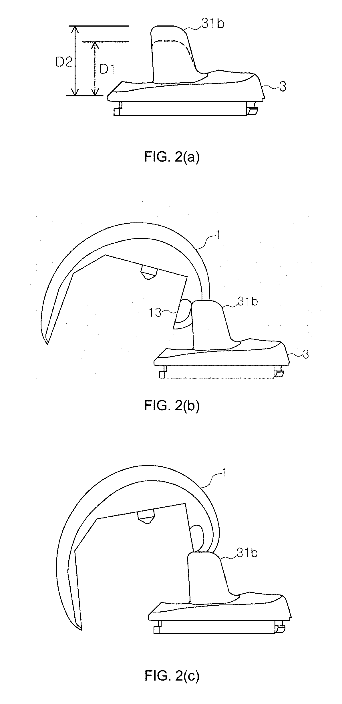
[0077]Further, the case of simply increasing the height of the post in the conventional artificial knee joint, as shown in FIG. 2(a), the basic shape of a post 31b is the same as the conventional artificial knee joint of FIG. 1, but by increasing the height of the post, a jump distance D2 is increased.
[0078]Accordingly, as shown in FIG. 2(b), the dislocation prevention effect of the thighbone coupling member is improved compared to the conventional artificial knee joint of FIG. 1, but as shown in FIG. 2(c), when a cam 13 of a thighbone coupling member 1 is dislocated, it is difficult for the thighbone coupling member to be restored to a normal state since an upper surface of the post 31b is formed in a horizontal plane.
[0079]Further, as shown in FIG. 2(d), the amount of bone to be cut in knee replacement surgery is considerably increased compared to the amount of bone to be cut shown in FIG. 1(c).
[0080]On the contrary, in the case of the present invention, as shown in FIG. 6(a), the inclined upper surface 311 and the lower curved surface 315 are provided and the jump distance D2 is increased; as shown in FIG. 6(b), the dislocation prevention effect of the thighbone coupling member 100 is improved compared to FIG. 1(b); as shown in FIG. 6(c), even when the cam 130 of the thighbone coupling member 100 is dislocated, the cam 130 descends along the upper surface 311, thereby facilitating restoration when dislocated, and through this, it is possible to prevent wear of the bearing member occurring in the restoration process when the thighbone coupling member 100 is dislocated.
[0081]Further, in terms of the jump distance of the artificial knee joint, as shown in FIG. 7, in the conventional artificial knee joint (a), the lower jump distance D1 is lower; in the case of simply increasing the height of the post in the conventional artificial knee joint (b), the jump distance D2 is increased, but it is difficult to efficiently prevent dislocation of the thighbone coupling member and is difficult to restore the thighbone coupling member when dislocated. In the case of the present invention (c), it is possible to prevent dislocation of a thighbone coupling member while increasing the jump distance D2, and the amount of bone to be cut is not increased, which will be described in detail with reference to FIGS. 8 to 10, hereinbelow.
[0082]FIG. 8 shows enlarged views of cam motions in a case where the thighbone coupling member is bent posteriorly, wherein the conventional artificial knee joint (a) has a structure in which it is difficult to prevent dislocation of the cam 13 when the thighbone coupling member is bent posteriorly, and on the contrary, the present invention (b) may firstly prevent dislocation of the thighbone coupling member since it is configured such that the cam 130 is stopped by the inflection point 314 by being prohibited from approaching the upper curved surface 312 over the lower curved surface 314.
[0083]FIG. 9 shows enlarged views of cam motions in a case where the thighbone coupling member is dislocated, wherein in the case of simply increasing the height of the post in the conventional artificial knee joint (a), since the upper surface of the post 31b is in a horizontal plane, it is difficult for the thighbone coupling member to be restored to a normal state after it is dislocated in cam motions. On the contrary, in the case of the present invention (b), since the cam 130 has a structure easily descending along the upper surface 311 that is inclined from anterior to posterior, it is easy to restore the thighbone coupling member when dislocated.
[0084]FIG. 10 shows amounts of bone to be cut in knee replacement surgery, wherein an amount of bone to be cut (b) in the case of simply increasing the height of the post is significantly increased compared to an amount of bone to be cut (a) in the conventional artificial knee joint, but an amount of bone to be cut(c) in the present invention is only slightly increased. Accordingly, the present invention has a structure that is capable of increasing a jump distance without increasing an amount of bone to be cut.
[0085]In the above description, although reference to the preferred embodiments has allowed the present invention to be described in more detail, it should be understood that the present invention is intended to cover not only the exemplary embodiments, but also various alternatives, modifications, equivalents and other embodiments that may be included within the spirit and scope of the present invention as defined by the appended claims.