Substrate liquid treatment apparatus, tank cleaning method and non-transitory storage medium

Active Publication Date: 2017-11-23
TOKYO ELECTRON LTD
View PDF3 Cites 4 Cited by
  • Summary
  • Abstract
  • Description
  • Claims
  • Application Information

AI Technical Summary

Benefits of technology

[0009]According to the foregoing embodiments of the present invention, since the tank is cleaned by discharging the cleaning liqui

Problems solved by technology

The tank is contaminated if the particles a

Method used


Image

  • Substrate liquid treatment apparatus, tank cleaning method and non-transitory storage medium
  • Substrate liquid treatment apparatus, tank cleaning method and non-transitory storage medium
  • Substrate liquid treatment apparatus, tank cleaning method and non-transitory storage medium

Examples


Embodiment Construction

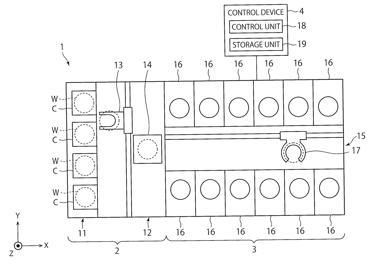
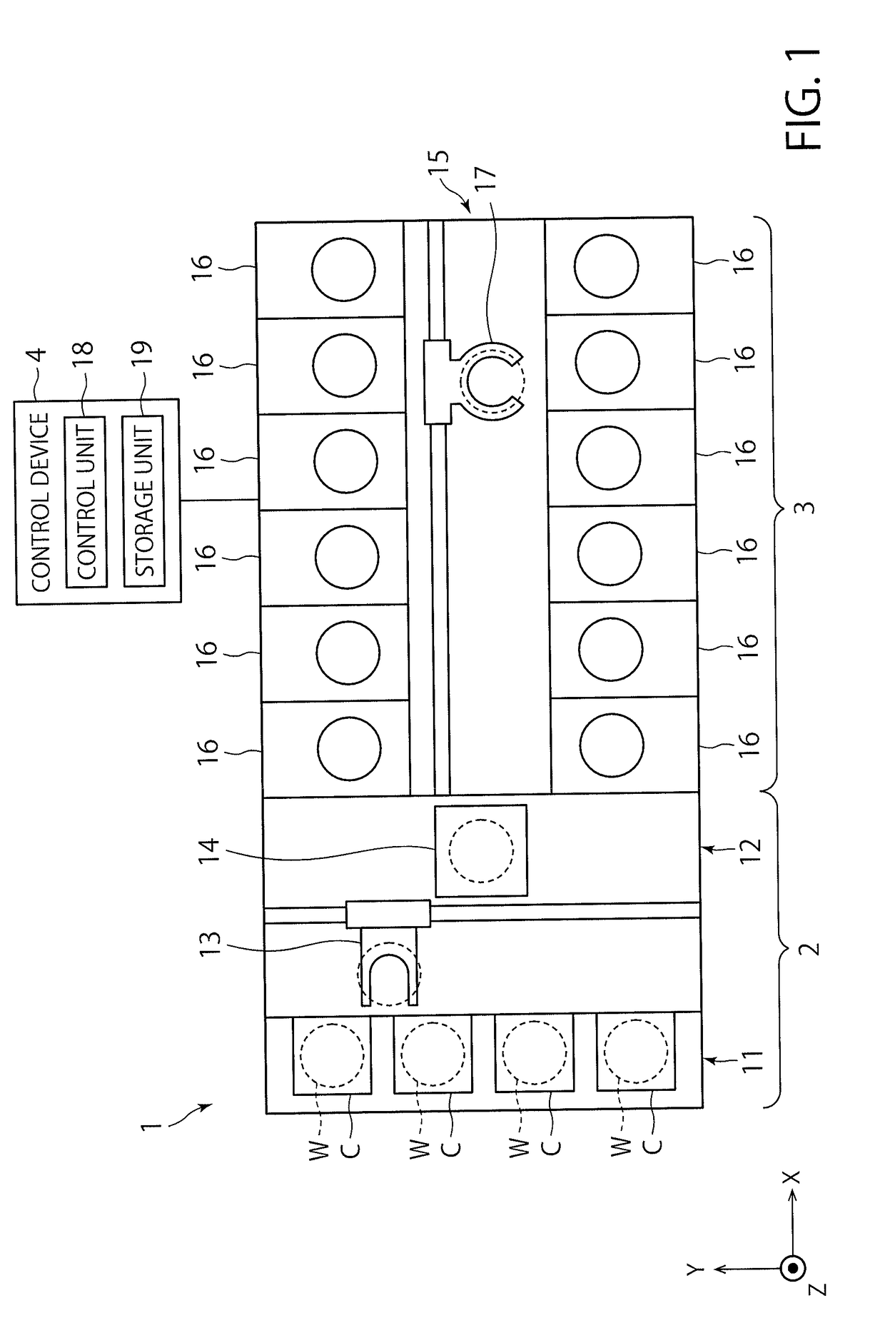
[0020]FIG. 1 is a plan view illustrating an outline of a substrate processing system provided with a processing unit according to an exemplary embodiment of the present disclosure. In the following, in order to clarify positional relationships, the X-axis, Y-axis and Z-axis which are orthogonal to each other will be defined. The positive Z-axis direction will be regarded as a vertically upward direction.

[0021]As illustrated in FIG. 1, a substrate processing system 1 includes a carry-in / out station 2 and a processing station 3. The carry-in / out station 2 and a processing station 3 are provided adjacent to each other.

[0022]The carry-in / out station 2 is provided with a carrier placing section 11 and a transfer section 12. In the carrier placing section 11, a plurality of carriers C is placed to accommodate a plurality of substrates (semiconductor wafers in the present exemplary embodiment) (hereinafter, referred to as “wafers W”) horizontally.

[0023]The transfer section 12 is provided a...


PUM


Abstract

In one embodiment, a substrate liquid treatment apparatus includes: a tank that stores a processing liquid; a circulation line connected to the tank, through which circulation line a circulation flow of the processing liquid that leaves the tank and then returns back to the tank; a processing unit that processes a substrate by supplying the processing liquid, distributed from the circulation line, to the substrate; a return line that returns, to the tank, the processing liquid discharged from the processing unit after being supplied to the substrate; a cleaning nozzle that discharges a cleaning liquid onto an inner wall surface of the tank to clean the inner wall surface by the cleaning liquid; and a cleaning line that supplies the cleaning liquid to the cleaning nozzle.

Description

CROSS-REFERENCE TO RELATED APPLICATIONS[0001]This application is based upon and claims the benefit of priority from Japanese Patent Application No. 2016-098977, filed on May 17, 2016, the entire contents of which are incorporated herein by reference.FIELD OF THE INVENTION[0002]The present invention relates to a technique of cleaning a tank that constitutes a processing liquid supply unit in a substrate liquid treatment apparatus.BACKGROUND ART[0003]In the manufacture of semiconductor devices, a substrate such as a semiconductor wafer is subjected to a liquid treatment such as a wet cleaning process, a wet etching process and so on. In a substrate liquid treatment apparatus that performs such liquid treatments, in order to facilitate supplying of a chemical liquid of a stable concentration and a stable temperature to a substrate, there is provided a processing liquid supply unit including a tank that stores a processing liquid, a circulation line connected to the tank, and a pluralit...

Claims


Application Information

Patent Timeline
IPC IPC(8): B08B9/032H01L21/67
CPCB08B9/0325H01L21/67023H01L21/67017H01L21/67075H01L21/67051B08B9/093H01L21/02052H01L21/6715
Inventor MIZOTA, SHOGO
Owner TOKYO ELECTRON LTD
Why Eureka
Try Eureka