Pumping system, vibration limiting device, and method

a technology of vibration limitation and pumping system, which is applied in the direction of pumping, positive displacement liquid engine, liquid fuel engine, etc., can solve the problems of eventually tend to occur due to mechanical fatigue and failure, and achieve complex vibrational phenomena that are difficult to even characterize, much less ameliora

Active Publication Date: 2017-11-23
CATERPILLAR INC
View PDF3 Cites 105 Cited by
  • Summary
  • Abstract
  • Description
  • Claims
  • Application Information

AI Technical Summary

Problems solved by technology

If excessive vibrations are not addressed, mechanical fatigue and failure eventually tends to occur.
Where multiple pieces of equipment are coupled together such as engines, transmissions, and drive...

Method used


Image

  • Pumping system, vibration limiting device, and method
  • Pumping system, vibration limiting device, and method
  • Pumping system, vibration limiting device, and method

Examples


Embodiment Construction

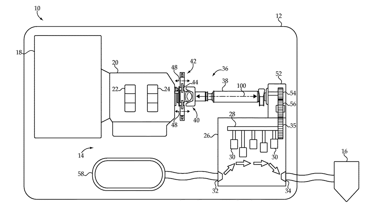
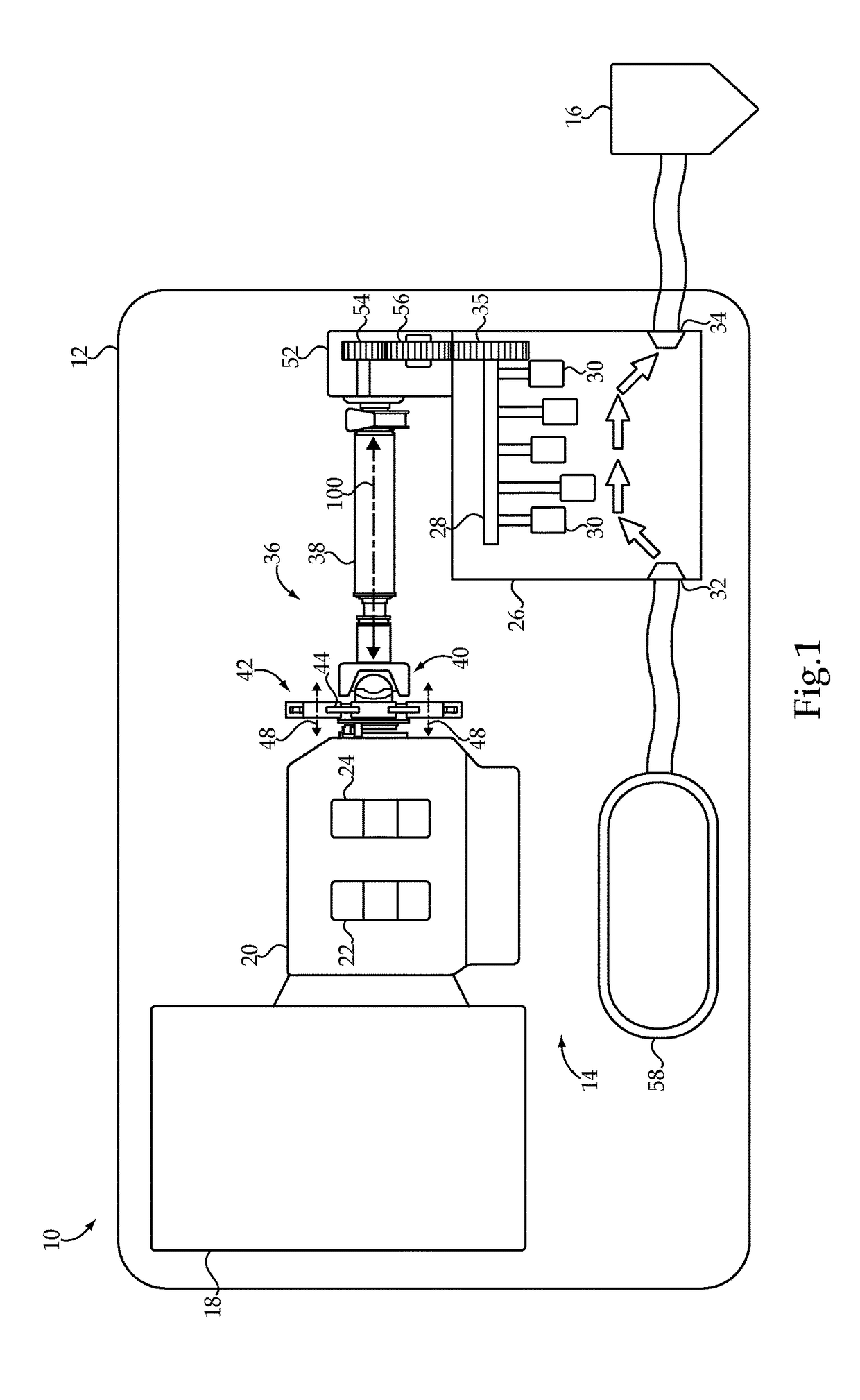
[0012]Referring to FIG. 1 there is shown a machinery rig 10 such as might be used in oilfield or gas field operations, according to one embodiment. Rig 10 may include a frame 12, which could be a vehicle trailer or the like, or a stationary platform, coupled with or having mounted thereon a plurality of components including a pumping system 14. In a practical implementation strategy, pumping system 14 can be coupled with a fluid injector 16 located at a wellhead that is structured to inject a fluid under pressure into a well for purposes of so-called hydraulic fracturing. In a practical implementation strategy, pumping system 14 may include or be coupled with a fluid supply, such as a cryogenic storage tank 58 or the like containing liquid nitrogen or a mixture containing liquid nitrogen.

[0013]Pumping system 14 further includes a source of rotary power such as an internal combustion engine 18, and a transmission 20 coupled with engine 18 and having a plurality of gears 22 and 24. Pu...


PUM


Abstract

A mechanism for limiting vibration amplitudes in a pumping system includes a plurality of pendulum absorbers coupled with a carrier and each having a pivoting range. The pendulum absorbers each further include a first and a second contact surface that contacts an outer peripheral surface of the carrier at limit stop positions, and each having a shape that is conforming with a shape of the outer peripheral surface. The pumping system may be used for pumping liquid nitrogen.

Description

TECHNICAL FIELD[0001]The present disclosure relates generally to vibration limiting mechanisms used in rotary machines, and more particularly to a pendulum damper mechanism for limiting torsional vibrations in a pumping system.BACKGROUND[0002]The challenges presented by mechanical vibrations in rotating machinery are likely as old as rotating machinery itself. Vibrations of interest in rotating machinery can typically be classified as either torsional or transverse. Transverse vibrations in this context can be generally understood as oscillations about an equilibrium point that deflect a rotating element in directions transverse to the axis about which the element is rotating. Torsional vibrations are rotational oscillations circumferentially about the axis of rotation. If excessive vibrations are not addressed, mechanical fatigue and failure eventually tends to occur.[0003]Various mechanisms are known for reducing or eliminating vibrations, either through dissipation of kinetic ene...

Claims


Application Information

Patent Timeline
IPC IPC(8): F04B53/00F04B19/22F04B17/05
CPCF04B53/003F04B19/22F04B17/05F04B1/053F04B9/04F04B53/001Y10T74/2128F16F15/145F04B53/004F04B39/0088
Inventor ROBINSON, ZACHARYBROSOWSKE, THOMAS
Owner CATERPILLAR INC
Why Eureka
Try Eureka