Damping Valve For A Vibration Damper

a technology of vibration damper and damping valve, which is applied in the direction of shock absorbers, springs/dampers, mechanical instruments, etc., can solve the problems of unfavorable pressure application point in lift-off, persistent negative effect of sticking effect on opening behavior,

Active Publication Date: 2017-11-23
ZF FRIEDRICHSHAFEN AG
View PDF5 Cites 1 Cited by
  • Summary
  • Abstract
  • Description
  • Claims
  • Application Information

AI Technical Summary

Benefits of technology

[0016]So as not to have to suffer any losses with respect to the magnitude of the pressure-impinged surface at the valve disk through the use of the at least one supporting segment, the supporting segment has a smaller height proceeding from the annular channel than the valve support surface. With respect to the height dimensioning, the outer valve support surface and the inner valve support surface are connected along a radial height line. The supporting segment t

Problems solved by technology

The construction according to DE 21 09 398 C3 has the functional disadvantage that the shape of the inhomogeneous width of the outer valve support surface leads to a sticki

Method used


Image

  • Damping Valve For A Vibration Damper
  • Damping Valve For A Vibration Damper
  • Damping Valve For A Vibration Damper

Examples


Embodiment Construction

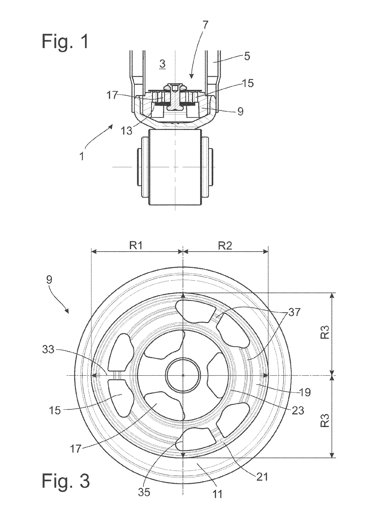
[0023]FIG. 1 shows, by way of example, a section from a vibration damper 1 constructed as a two-tube damper that has a damping valve 7 between a working chamber 3 filled with damping medium and a compensation space 5. In principle, the damping valve 7 can also be used for a piston rod or as pre-valve for an adjustable damping valve. The possible applications are not limited to the graphic representation or the above-mentioned cases.

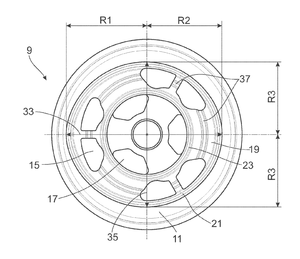
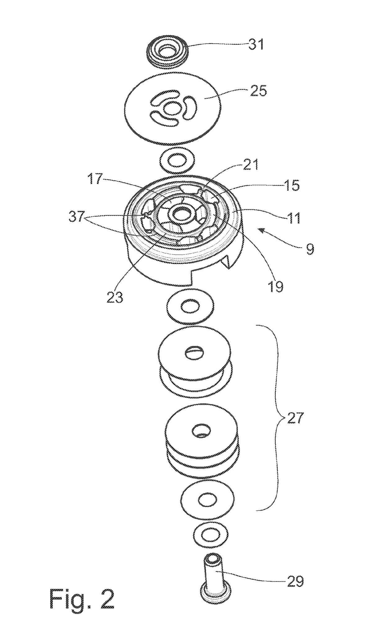
[0024]As can be seen more clearly when viewed in conjunction with FIG. 2, the damping valve 7 has a damping valve body 9 having two cover sides 11, 13. At least one passage channel 15, 17 connects the two cover sides 11, 13. In the present embodiment example, passage channels 15 are available for a first flow direction proceeding from the compensation space into the working chamber 3 and passage channels 17 are available for a flow proceeding from working chamber 3 into the compensation space 5. The quantity, shape and size of the passage channels are dep...


PUM


Abstract

Damping valve having a damping valve body with at least one passage channel between two cover sides. An outlet opening of the passage channel leads into a cover-side annular channel which is limited by an outer annular valve support surface and by an inner annular valve support surface, the at least one annular valve support surface for at least one valve disk has a substantially constant width along the circumference, and the annular channel has a varying width along the circumference, and at least one valve support surface has a varying radius of curvature along the circumference.

Description

CROSS REFERENCE TO RELATED APPLICATIONS[0001]This is a U.S. national stage of application No. PCT / EP2015 / 073502, filed on Oct. 12, 2015. Priority is claimed on German Application No. DE102014223086.1, filed Nov. 12, 2014, the content of which is incorporated here by reference.BACKGROUND OF THE INVENTION1. Field of the Invention[0002]The invention is directed to a damping valve for a vibration damper.2. Description of the Prior Art[0003]DE 21 09 398 C3 describes a damping valve for a vibration damper. The damping valve comprises a damping valve body with a cover side having an eccentric, circular ring-shaped valve support surface. Constructed at a radial distance is an inner circular ring-shaped valve support surface that is oriented eccentrically in the same orientation. This results in an eccentric annular channel with a constant radial width. A centric valve disk covering the annular channel accordingly has a pressure area radius which varies along the circumference. A defined lif...

Claims


Application Information

Patent Timeline
IPC IPC(8): F16F9/348F16K47/10
CPCF16K47/10F16F9/348
Inventor HOLTMANN, GUIDOEICH, ACHIMHENRICHS, JURGENROSSELER, JORGKNEZEVIC, ALEKSANDER
Owner ZF FRIEDRICHSHAFEN AG
Why Eureka
Try Eureka