System and Method for Reducing Nitrogen Content of GSP/Expander Product Streams for Pipeline Transport

a technology of gsp/expander and product stream, which is applied in the direction of liquefaction, machine-to-machine/machine-type communication service, etc., can solve the problems of high capital and operating costs of known nru systems, high capital and operating costs associated with various pieces of equipment, and achieve the effect of facilitating the economically efficient removal of nitrogen and nitrogen conten

Active Publication Date: 2017-11-23
BCCK HLDG CO
View PDF5 Cites 3 Cited by
  • Summary
  • Abstract
  • Description
  • Claims
  • Application Information

AI Technical Summary

Benefits of technology

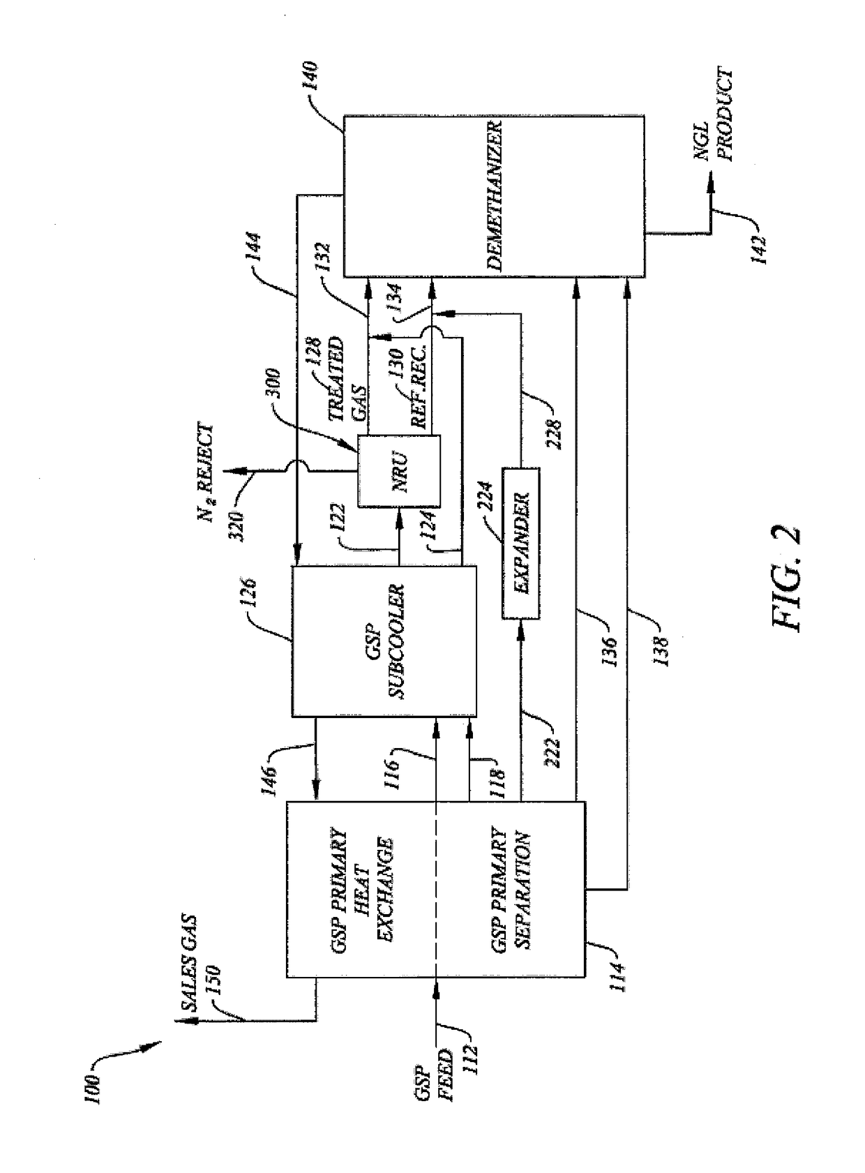
The patent discusses a system and method for economically removing nitrogen from methane gas using a modified form of a conventional system. By integrating a nitrogen removal unit (NRU) into a gas processing plant, the system can produce a sales gas that meets the specifications of a particular pipeline without requiring additional treatment. The NRU reduces nitrogen content in the sales gas, which is then reintroduced into the plant for further processing. This system has lower costs and higher efficiency compared to standalone NRU systems. The NRU system and method may also enhance the recovery of natural gas liquids (NGLs) from the gas stream.

Problems solved by technology

Although the present system and method has the disadvantage of higher capital costs associated with additional equipment for the NRU and higher operating costs for that equipment, compared to a GSP operation without an NRU, the costs of such are sufficiently offset by the savings in having sales gas within pipeline specification and savings in operating costs achieved by strategically placing the NRU within the GSP operation to take advantage of inter-operational efficiencies, such as heat exchange between process stream.
Such known NRU systems have higher capital and operating costs associated with various pieces of equipment typically used in such systems, such as the additional fractionating column (in the two-column system), equipment to remove water and carbon dioxide, and multiple heat exchangers.

Method used


Image

  • System and Method for Reducing Nitrogen Content of GSP/Expander Product Streams for Pipeline Transport
  • System and Method for Reducing Nitrogen Content of GSP/Expander Product Streams for Pipeline Transport
  • System and Method for Reducing Nitrogen Content of GSP/Expander Product Streams for Pipeline Transport

Examples


example

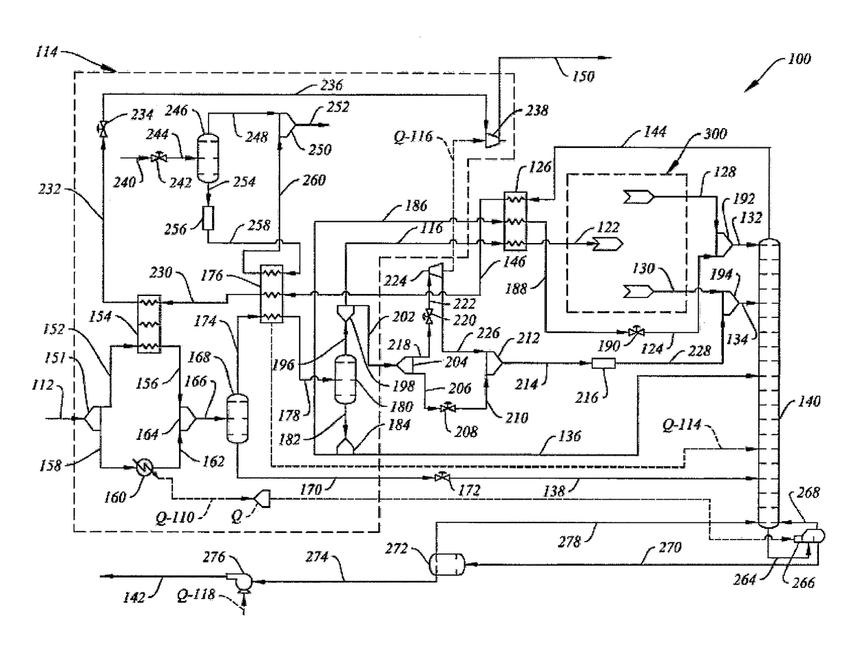
[0029]The flow rates, temperatures and pressures of various flow streams referred to in connection with the discussion of the system and method of the invention in relation to FIGS. 4 and 5, for a GSP feed stream flow rate of 100 MMSCFD and containing 4% nitrogen, 70% methane, 14.7% ethane, and 8.4% propane appear in Table 1 below. The values for the energy streams referred to in connection with the discussions of the system and method of the invention in relation to FIGS. 4 and 5 appear in Table 2 below. The values discussed herein and in the tables below are approximate values.

TABLE 1FLOW STREAM PROPERTIESStreamTemper-Reference%%%%Flow RateaturePressureNumeralN2CH4C2H6C3H8(lbmol / h)(deg. F.)(psig)112469.914.88.410979.8120750.31165.582.89.32.24057.2−40733.31225.582.89.32.24057.2−97.7728.3124144.846.420.60.34−121.12151280.5879.92.32919.1−162.22101300.5879.92.3899.6−902151320.5879.92.42919.5−162.22101344.483.79.42.24219.1−109.5215136144.826.420.63395.2−40733.31380.522.418.826.7207.631...


PUM


Abstract

A system and method for removing nitrogen from an intermediate stream in a gas subcooled process operation that processes natural gas into a sales gas stream and a natural gas liquids stream. The system and method of the invention are particularly suitable for use with gas subcooled process operations where the sales gas stream exceeds pipeline nitrogen specifications by up to about 3%, such as for reducing the nitrogen content of sales gas streams to levels permissible for pipeline transport.

Description

CROSS REFERENCE TO RELATED APPLICATIONS[0001]This application is a divisional of U.S. application Ser. No. 13 / 546,532 filed on Jun. 11, 2012.BACKGROUND OF THE INVENTION1. Field of the Invention[0002]This invention relates to a system and method for separating nitrogen from methane and other components of natural gas streams being processed into a sales gas stream and a natural gas liquids (NGL) stream by the known gas subcooled / expander process (GSP / expander process or simply GSP). The system and method of the invention are particularly suitable for use in connection with natural gas streams where the processed sales gas stream contains nitrogen in an amount that exceeds pipeline specifications.2. Description of Related Art[0003]Nitrogen contamination is a frequently encountered problem in the production of natural gas. Transporting pipelines typically do not accept natural gas containing more than about 4 mole percent inerts, such as nitrogen. Estimates indicate that as much as 25%...

Claims


Application Information

Patent Timeline
Patent Type & Authority Applications(United States)
IPC IPC(8): F25J3/02F25J3/08
CPCF25J3/0257F25J3/08F25J3/0209F25J3/0233F25J3/0238F25J2200/04F25J2200/40F25J2200/70F25J2200/74F25J2205/04F25J2230/60F25J2240/02F25J2245/02F25J2270/02F25J2270/60Y02C20/40H04L67/61H04W4/70H04W76/10H04L43/0852H04L43/0888H04L67/303H04L69/24H04W24/02H04W28/18H04W88/02H04W88/08
Inventor BUTTS, RAYBURN C.
Owner BCCK HLDG CO
Why Eureka
Try Eureka