Supercharge Your Innovation With Domain-Expert AI Agents!

Track for routing an optical fiber

a technology of optical fiber and track, applied in the field of fiber optic communication systems, can solve the problems of unsightly measures for securing optical fiber, uneven application of adhesives and caulking, and little protection, if any, of optical fiber, and achieve the effect of facilitating the installation of the track

Active Publication Date: 2017-11-23
TII NETWORK TECH
View PDF22 Cites 2 Cited by
  • Summary
  • Abstract
  • Description
  • Claims
  • Application Information

AI Technical Summary

Benefits of technology

The present invention provides a track for routing optical fibers that protects them from damage, is aesthetically pleasing, and easy to install. The track has an adhesive-applied back wall and a slot in the front wall for inserting and holding the optical fiber in place without damage. The technical effects of this invention include improved protection and ease of installation for optical fibers.

Problems solved by technology

Such measures for securing the optical fiber are quite unsightly.
Adhesives and caulking are often unevenly applied and provide little protection, if any, to the optical fiber.
A tape covering is also unsightly, may exhibit wrinkles when applied, and the edges of the tape may lift as it ages.
Tape also provides very little protection for the optical fiber, and may be difficult to remove or reposition without damaging the sensitive optical fiber it covers.
Also, none of the above-described methods provides for the required minimum bend radius when routing the optical fiber around corners or edges of walls, doors and windows.

Method used


Image

  • Track for routing an optical fiber
  • Track for routing an optical fiber
  • Track for routing an optical fiber

Examples


Embodiment Construction

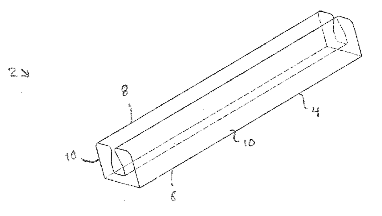
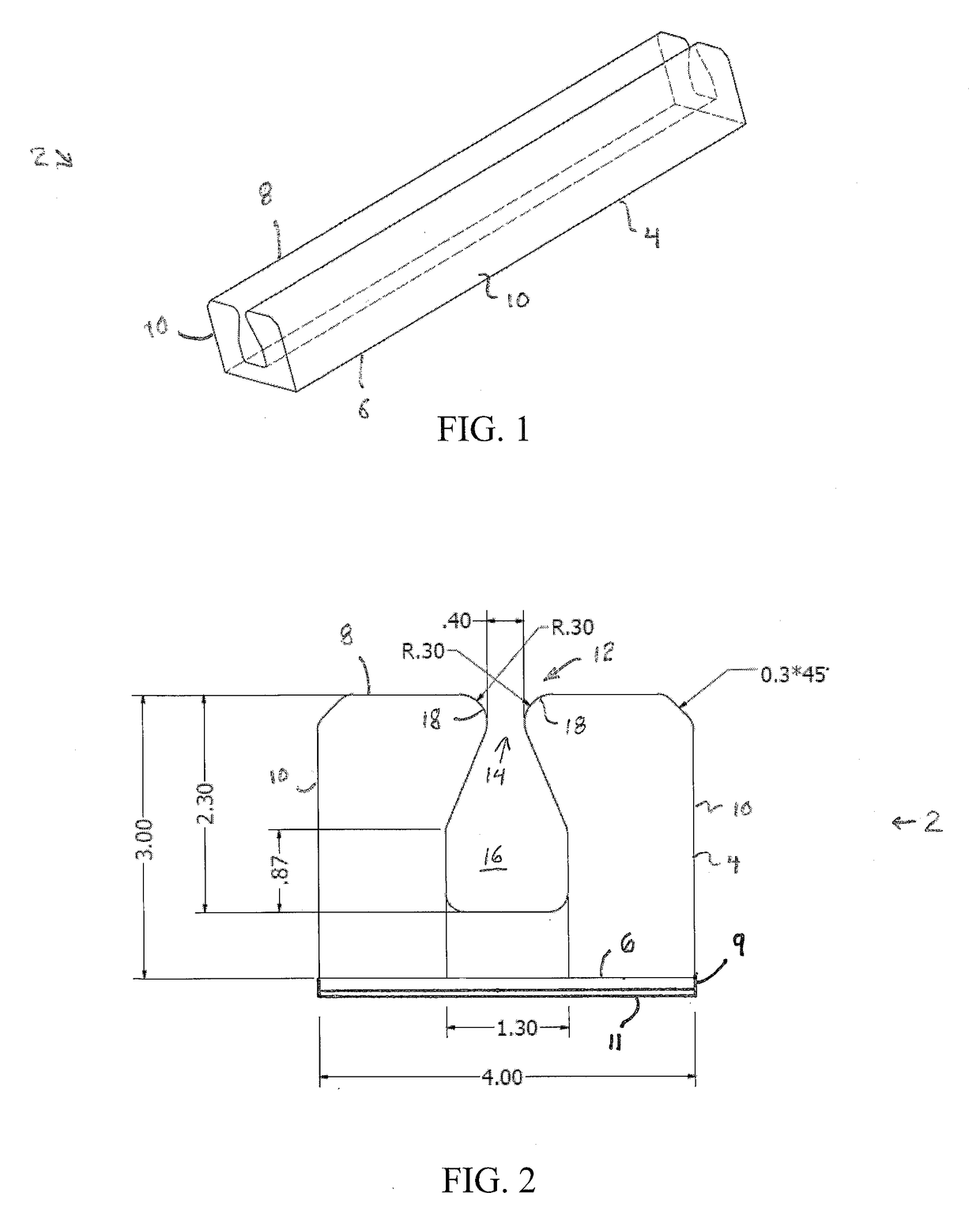
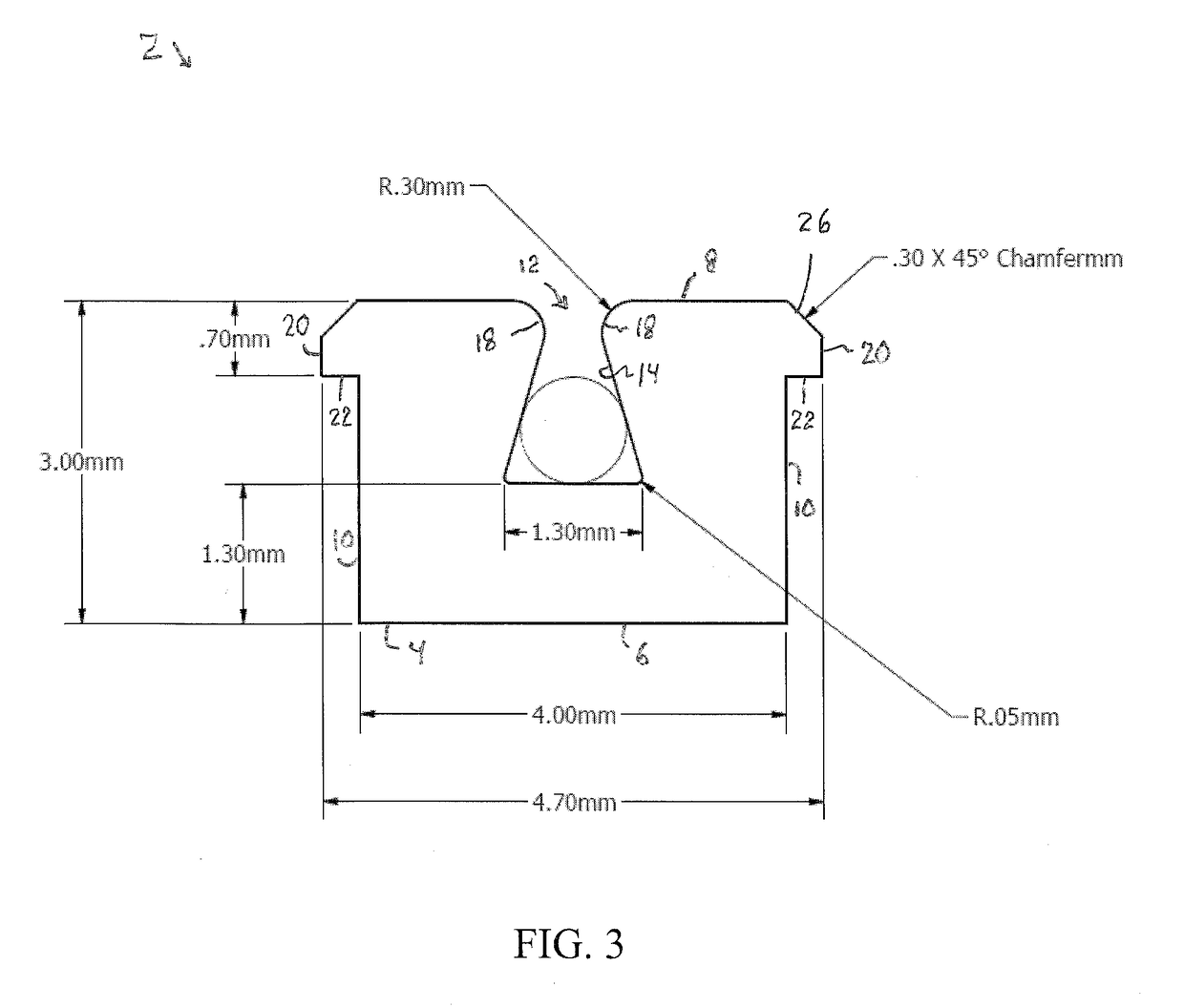
[0024]Initially referring to FIGS. 1-4 of the drawings, it will be seen that a track 2 for routing an optical fiber within a residential or commercial premises includes an elongated member 4, which is generally rectangular in transverse cross-section, having a back wall 6, a front wall 8 situated opposite the back wall 6, and opposite lateral side walls 10. The back wall 6 includes an adhesive layer 9 that is covered by a removable plastic backing 11. The plastic backing 11 may be removed by a technician or end-user to expose the adhesive layer 9 on the back wall 6 of the track 2 (i.e., the elongated member 4) when the technician or end-user is about to apply the track 2 to an exposed surface of an interior wall of the residential or commercial premises. The track 2, and more precisely, the elongated member 4, is preferably made from a soft polyvinylchloride material or from a soft polyethylene material, and is preferably clear so that the color of the wall on which it is mounted sh...


PUM


Abstract

A track system for routing an optical fiber includes a track for selectively retaining the optical fiber therein, a cover piece which is mounted to the track, and a corner piece which is mounted to the track. The track is formed as an elongated member and includes a pair of legs that are spaced apart from each other to define a slot and an internal channel into which the optical fiber is received. The cover piece is mountable to the track to help retain the optical fiber in the track.

Description

CROSS-REFERENCE TO RELATED APPLICATIONS[0001]This application is related to U.S. Provisional Patent Application Serial No. 62 / 338,819, filed on May 19, 2016, and entitled “Track for Routing an Optical Fiber”, the disclosure of which is hereby incorporated by reference and on which priority is hereby claimed.BACKGROUND OF THE INVENTIONField of the Invention[0002]The present invention generally relates to fiber optic communications systems, and more particularly relates to devices and techniques for routing optical fibers and cables within residential or commercial premises.Description of the Prior Art[0003]Oftentimes, a technician of an internet / cable television service provider needs to install fiber optic cables within the premises of an end-user, such as a residential house, apartment or commercial office building. In doing so, sometimes it is necessary to route a single optical fiber strand within the premises on the surface of the interior walls of the premises, and around corne...

Claims


Application Information

Patent Timeline
IPC IPC(8): G02B6/44
CPCG02B6/4459G02B6/4466G02B6/4429G02B6/475G02B6/364G02B6/4471
Inventor MARCOU, JEAN-CLAUDEBARBO, VINCENTFOLEY, DAVID E.FAY, WALTERFEEZER, ALEX CLIFTONMEHTA, PARAG
Owner TII NETWORK TECH
Features
  • R&D
  • Intellectual Property
  • Life Sciences
  • Materials
  • Tech Scout
  • Unparalleled Data Quality
  • Higher Quality Content
  • 60% Fewer Hallucinations
Learn More