
Systems and methods for adjacent vertebral fixation

a technology for adjacent vertebrae and fixation, which is applied in the field of adjacent vertebrae fixation, can solve problems such as inability to securely hold plates

Active Publication Date: 2017-11-30
ABSOLUTE ADVANTAGE MEDICAL
View PDF7 Cites 23 Cited by
  • Summary
  • Abstract
  • Description
  • Claims
  • Application Information

AI Technical Summary

Benefits of technology

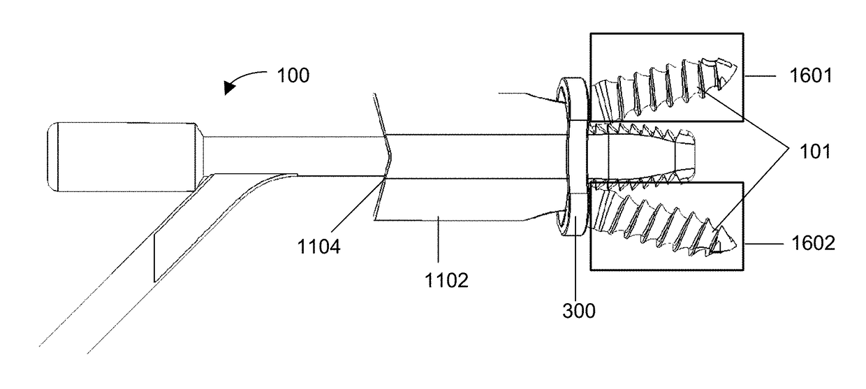
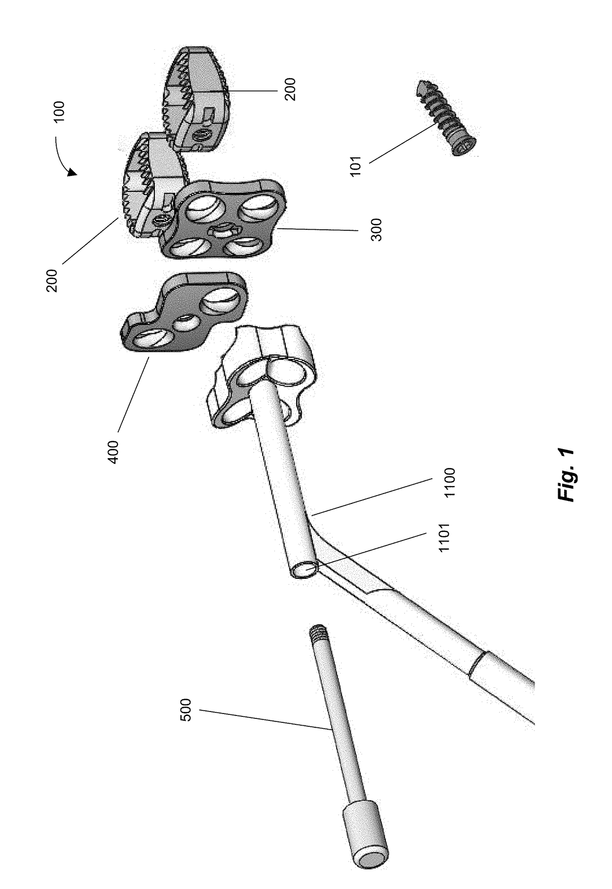
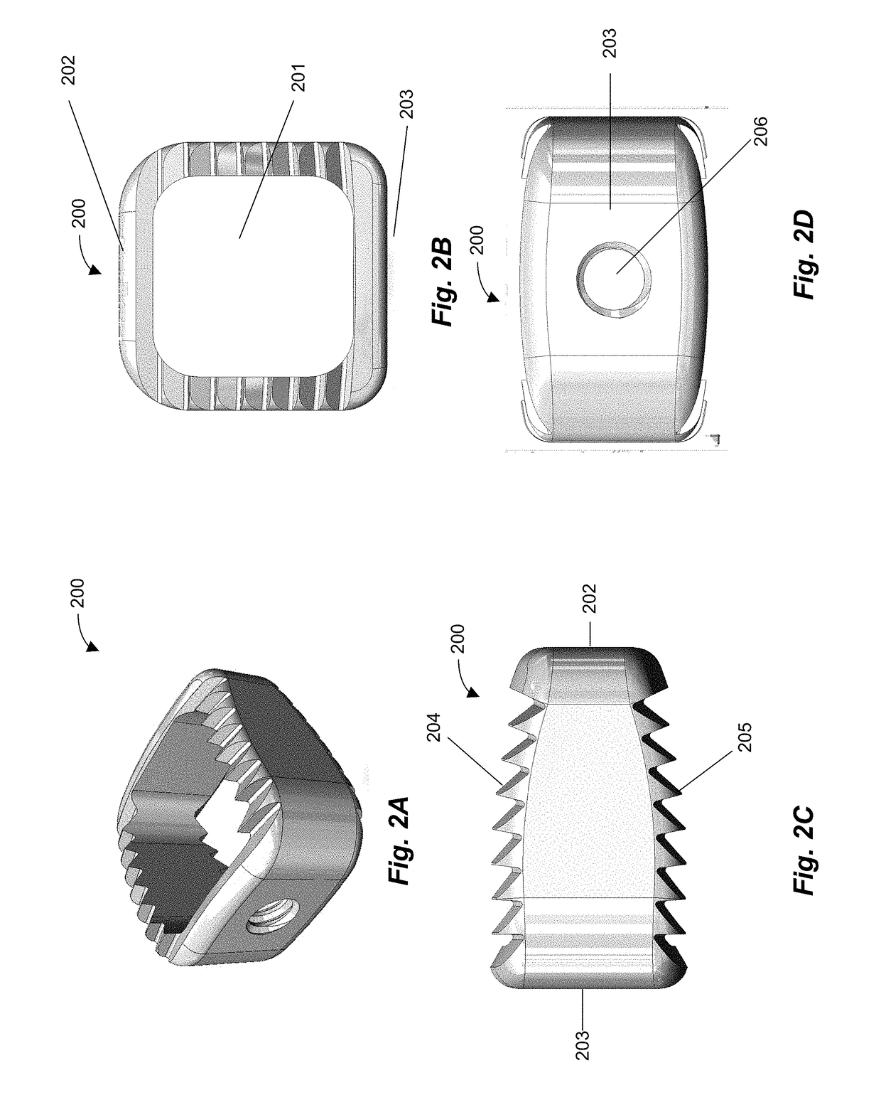
The present invention is a vertebral stabilization system that includes a positioning handle, a cage-plate holder, a drill guide assembly, an intervertebral cage, and a screw. The positioning handle has a shaft with a distal end and a proximal end, and the distal end has a first locking mechanism. The cage-plate holder has a handle channel with a diameter that matches the diameter of the shaft's distal end. The drill guide assembly has an opening that can hold a drill, and the intervertebral cage has an opening that can lock with the first locking mechanism. The system allows for stable stabilization of the vertebral column during spine surgeries. The positioning handle has a fluid channel for delivering fluid to the intervertebral cage. The cage-plate holder has a handle that can hold a drill guide assembly, and the drill guide assembly has a plurality of openings that align with the openings of the intervertebral stabilization plate. The system also includes a screw that can be inserted through the drill guide assembly and into the intervertebral cage.

Problems solved by technology

If they are small, they do not hold the plate securely.

Method used


Image

  • Systems and methods for adjacent vertebral fixation
  • Systems and methods for adjacent vertebral fixation
  • Systems and methods for adjacent vertebral fixation

Examples


Embodiment Construction

[0041]Although example embodiments of the disclosed technology are explained in detail, it is to be understood that other embodiments are contemplated. Accordingly, it is not intended that the invention is limited in its scope to the details of construction and arrangement of components set forth in the following description or illustrated in the drawings. The invention is capable of other embodiments and of being practiced or carried out in various ways. Also, in describing the preferred embodiments, specific terminology will be resorted to for the sake of clarity.

[0042]It should also be noted that, as used in the specification and the appended claims, the singular forms “a,”“an” and “the” include plural references unless the context clearly dictates otherwise. References to a composition containing “a” constituent is intended to include other constituents in addition to the one named.

[0043]Also, in describing the preferred embodiments, terminology will be resorted to for the sake ...


PUM


Abstract

The present invention relates to systems and methods for spinal fusion procedures that can allow all components of the spinal fusion procedure to be inserted into the wound of a patient at once, and can thus minimize the number of components that must be separately inserted into a wound. This can be accomplished by providing a intervertebral fixation system that allows an intervertebral cage, vertebral fixation plate, and drill guides to be assembled into a single unit prior to insertion into a patient.

Description

CROSS REFERENCE TO RELATED APPLICATIONS[0001]This application claims benefit, under 35 U.S.C. §119(e), to U.S. Provisional Application No. 62 / 343,483, filed 31 May 2016. The entire contents and substance of the above application are hereby incorporated by reference as if fully set forth herein.TECHNICAL FIELD[0002]The present disclosed technology is primarily applicable to adjacent vertebral fixation; however it is also applicable to the fields of orthopedic surgery and biotechnology, as would be recognized by a person of ordinary skill in the art.BACKGROUND[0003]In the field of adjacent vertebral fixation, temporary pins have many disadvantages. If they are small, they do not hold the plate securely. If they are large, the same is often true but they also create cavities in the vertebral bodies. Additionally, it is preferable for the plate to be flush with the vertebral bodies to prevent the plate from acting as a lever and pulling out the pins when the plate is manipulated.[0004]W...

Claims


Application Information

Patent Timeline
IPC IPC(8): A61B17/70A61F2/44A61F2/46A61B17/56A61B17/86
CPCA61B17/70A61F2/4611A61F2/4455A61F2/442A61F2/46A61F2002/4623A61B17/86A61B17/56A61F2002/448A61F2220/0025A61B2017/564A61B17/7059A61B17/1728A61B17/1757A61B17/8042A61F2/4603
Inventor BULLARD, DENNIS E.
Owner ABSOLUTE ADVANTAGE MEDICAL
Learn More