Current detector
a current detector and detector technology, applied in the field of current detectors, can solve the problems of increasing the size of power converters cannot be reduced, and the height of current detectors is inevitably increased, so as to reduce the occupied volume and reduce the mechanical strength
- Summary
- Abstract
- Description
- Claims
- Application Information
AI Technical Summary
Benefits of technology
Problems solved by technology
Method used
Image
Examples
first embodiment
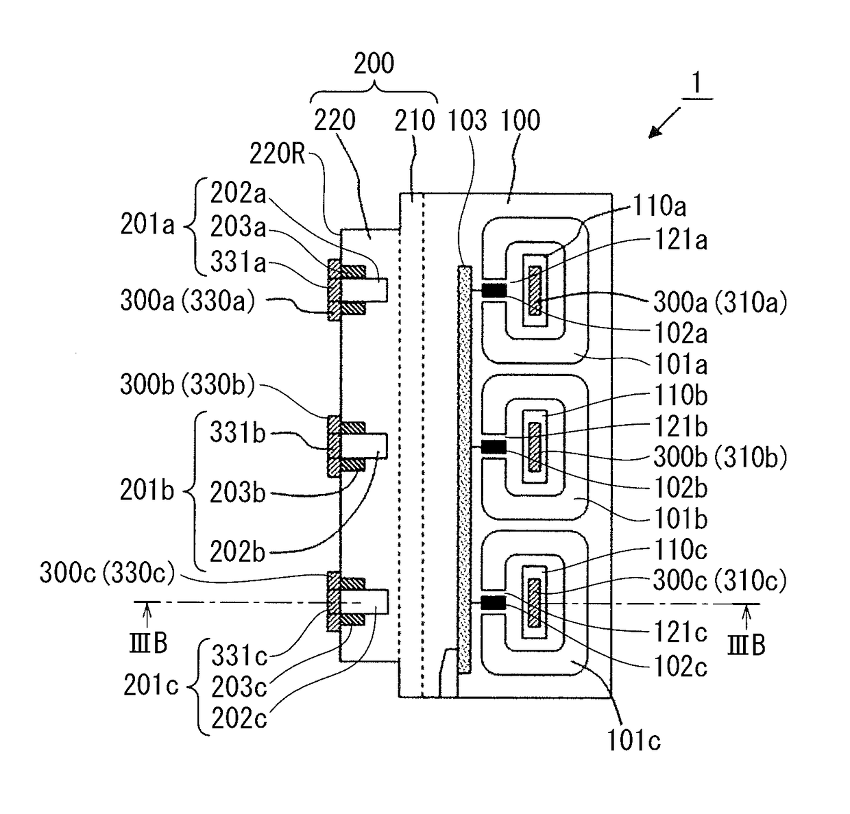
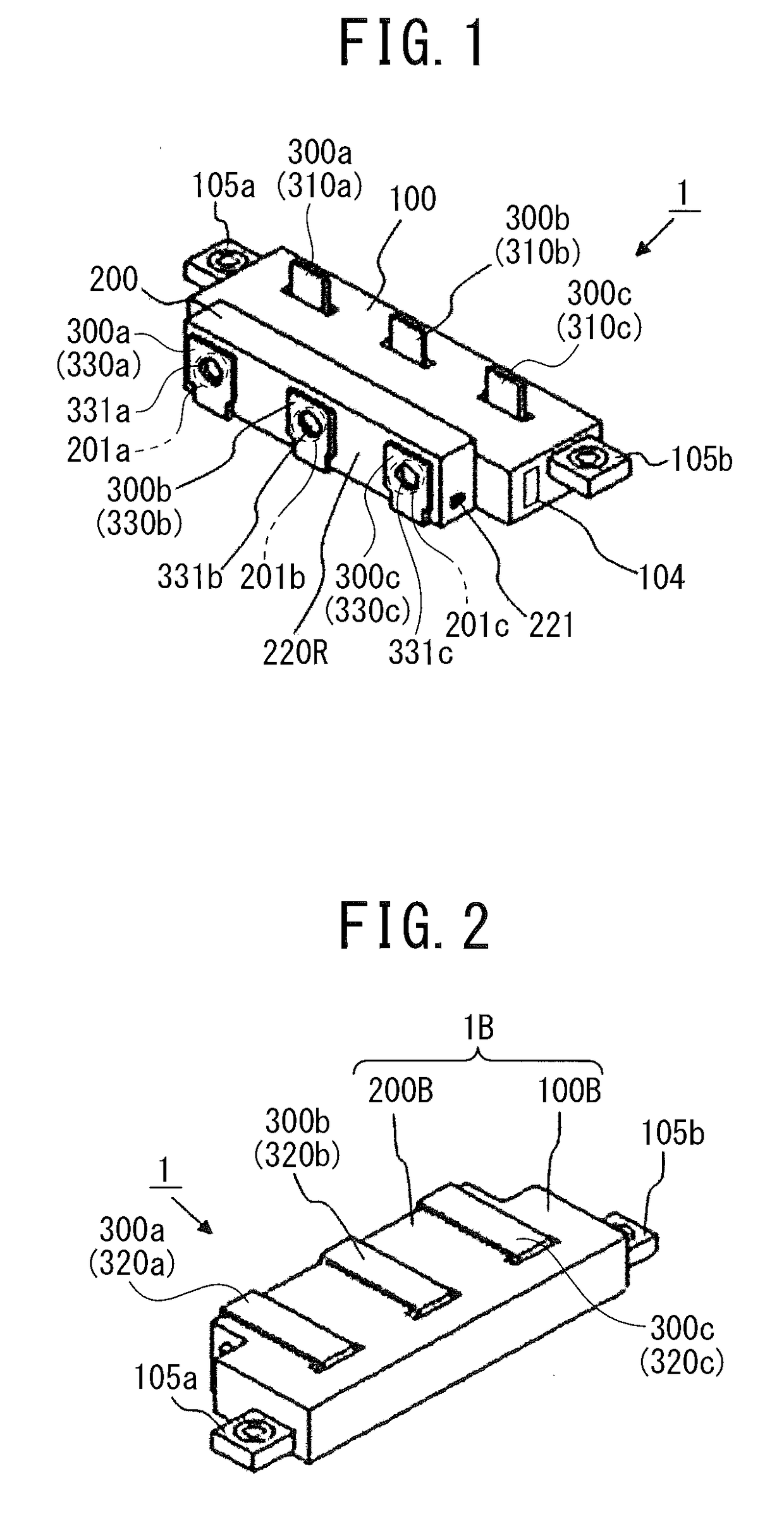
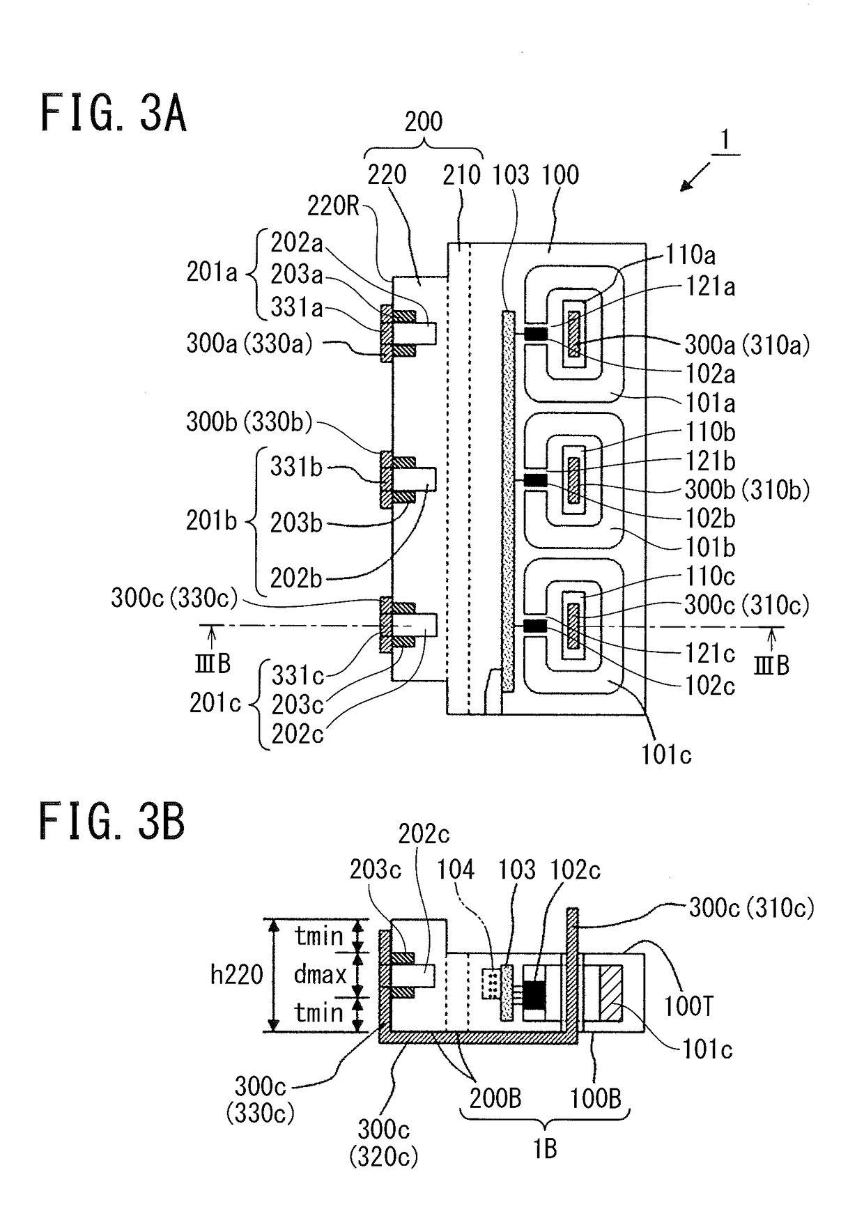
[0022]As illustrated in FIG. 1 and FIG. 2, a current detector 1 according to the first embodiment includes a current detection unit 100, a terminal block 200, and three conductor bars 300a, 300b, and 300c. The current detection unit 100 has a substantially rectangular parallelepiped including an installation surface 100B. As used herein, a direction vertical to the longitudinal direction of the installation surface 100B is referred to as “the height direction”. The installation surface 100B is not always required to be brought in close contact with an opposed surface on which the installation surface 100B is to be placed.
[0023]As illustrated in FIG. 3A and FIG. 3B, the current detection unit 100 includes triple ring-shaped cores 101a, 101b, and 101c made of magnetic material and having gaps 121a, 121b, and 121c, triple magnetic-flux-density detection-elements 102a, 102b, and 102c located in the gaps 121a, 121b, and 121c, a circuit board 103 in which the magnetic-flux-density detecti...
second embodiment
[0043]A current detector 2 according to the second embodiment differs from the current detector 1 according to the first embodiment only in the positions of the triple terminal connecting portions 201a, 201b, and 201c, as illustrated in FIG. 4A and FIG. 4B.
[0044]The terminal connecting portions 201a, 201b, and 201c respectively include triple terminal connection holes 202a, 202b, and 202c having a substantially cylindrical shape provided on the installation surface 200B of the terminal block 200, triple nuts 203a, 203b, and 203c buried in opening ends of the terminal connection holes 202a, 202b, and 202c, and triple penetration holes 321a, 321b, and 321c open on the second conductors 320a, 320b, and 320c of the corresponding conductor bars 300a, 300b, and 300c.
[0045]The width w200, or the length measured in the short-side direction, of the terminal block 200 is set greater than the sum of the resin thickness tmin and the maximum diameter dmax of the terminal connection holes. There...
PUM
 Abstract
Description
Claims
Application Information
 - R&D
- Intellectual Property
- Life Sciences
- Materials
- Tech Scout
- Unparalleled Data Quality
- Higher Quality Content
- 60% Fewer Hallucinations
Browse by: Latest US Patents, China's latest patents, Technical Efficacy Thesaurus, Application Domain, Technology Topic, Popular Technical Reports.
© 2025 PatSnap. All rights reserved.Legal|Privacy policy|Modern Slavery Act Transparency Statement|Sitemap|About US| Contact US: help@patsnap.com


