Electric motor having balance structure and machine tool equipped with the electric motor

a technology of electric motors and balance structures, which is applied in the direction of mechanical equipment, cooling/ventilation arrangements, vibration suppression adjustments, etc., can solve the problems of inability to adjust balance, and achieve easy and high-precision balance adjustment

Active Publication Date: 2017-11-30
FANUC LTD
View PDF0 Cites 2 Cited by
  • Summary
  • Abstract
  • Description
  • Claims
  • Application Information

AI Technical Summary

Benefits of technology

[0015]According to the present invention, it is possible to provide an electric motor enabling easy and high-precision balance correction, and a machine tool equipped with this electric motor.

Problems solved by technology

However, when coupling an electric motor to the spindle or the like of a machine tool, since the labyrinth structure will be arranged within the spindle head, balance correction has not been possible after coupling.
For this reason, balance correction has not been possible without removing and disassembling the cooling fan, etc.

Method used


Image

  • Electric motor having balance structure and machine tool equipped with the electric motor
  • Electric motor having balance structure and machine tool equipped with the electric motor
  • Electric motor having balance structure and machine tool equipped with the electric motor

Examples


first embodiment

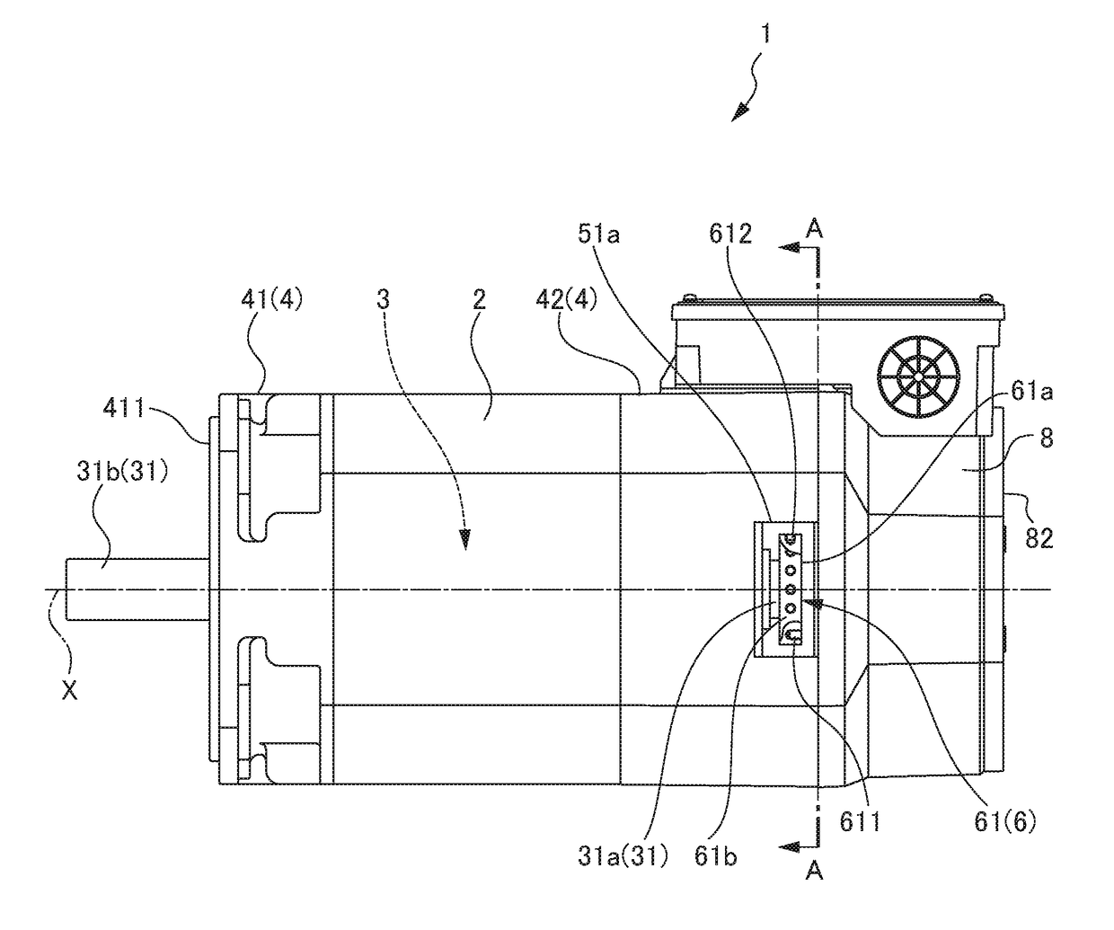
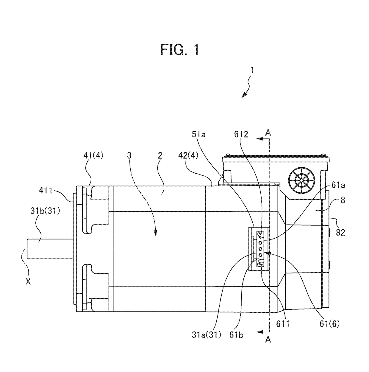
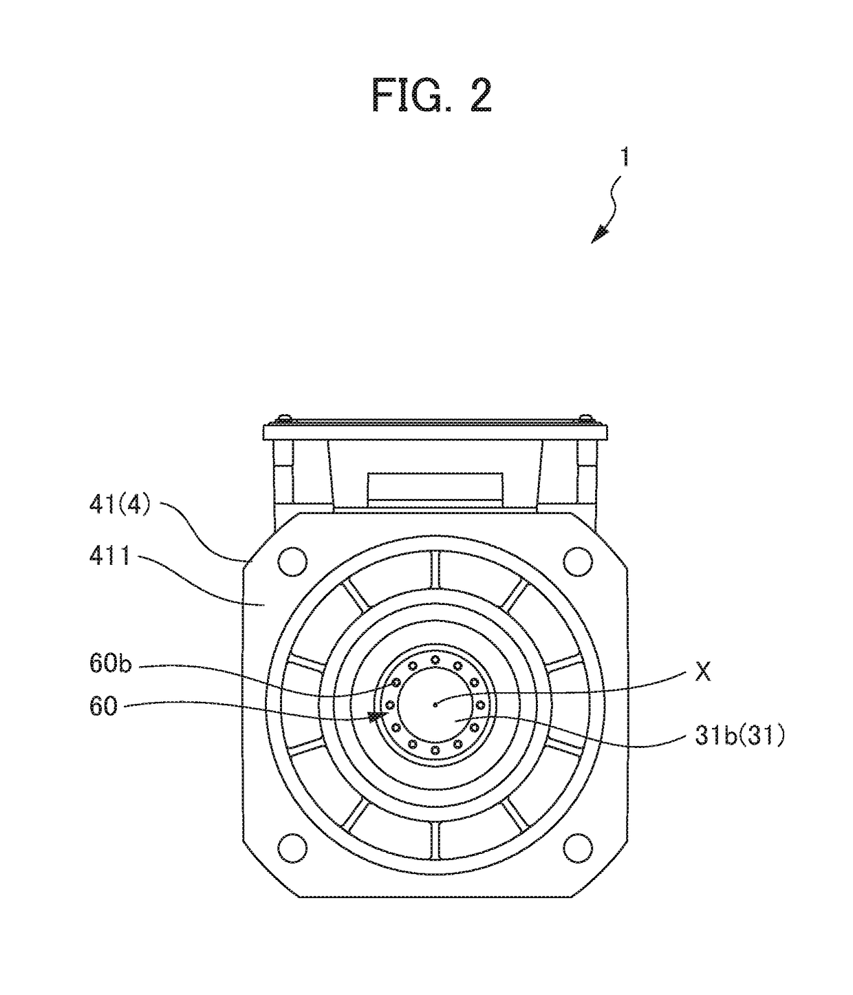
[0040]FIG. 1 is a side view of an electric motor 1 according to a first embodiment; FIG. 2 is a drawing viewing the electric motor 1 according to the first embodiment from forward in the axial direction. FIG. 3 is a drawing viewing the electric motor 1 according to the first embodiment from rearward in the axial direction. FIG. 4 is a partial sectional view of FIG. 1; FIG. 5 is a partial sectional view of FIG. 2; FIG. 6 is a cross-sectional view along the line A-A in FIG. 1; and FIG. 7 is a view showing a state removing a first cover member 44 in FIG. 6. In addition, FIG. 8 is a bottom view of an electric motor 1A according to a modified example of the first embodiment. FIG. 9 is a cross-sectional view along the line B-B in FIG. 8, and FIG. 10 is a view showing a state removing a first cover member 44A of FIG. 9. In addition, FIG. 11 is a partial sectional side view when coupling the electric motor 1 according to the first embodiment to a spindle 11 of a machine tool 10.

[0041]Herein...

second embodiment

[0065]FIG. 12 is a side view of an electric motor 1B according to a second embodiment. FIG. 13 is a drawing viewing the electric motor 1B according to the second embodiment from forwards in the axial direction. FIG. 14 is view showing an aspect of removing a second cover member 45 in FIG. 13. FIG. 15 is a partial cross-sectional view of FIG. 12; FIG. 16 is a partial cross-sectional view of FIG. 13; and FIG. 17 is a cross-sectional view along the line C-C in FIG. 12. In addition, FIG. 18 is a side view of an electric motor 1C according to a modified example of the second embodiment. FIG. 19 is a bottom view of the electric motor 1C according to a modified example of the second embodiment. FIG. 20 is a drawing viewing the electric motor 1C according to a modified example of the second embodiment from forward in the axial direction. FIG. 21 is a view showing an aspect removing a second cover member 45 in FIG. 20. FIG. 22 is a partial cross-sectional side view when coupling the electric...

third embodiment

[0076]FIG. 23 is a side view of an electric motor 1D according to a third embodiment. The electric motor 1D according to the present embodiment is achieved by combining the first embodiment and the second embodiment. In other words, it is the same configuration as the first embodiment and second embodiment, except for differing in the point of openings being provided in both the back housing and front housing, and the point of both of the first balance correction component 61 and the second balance correction component 62 being provided. It should be noted that, as a modified example of the present embodiment, it is possible to adopt a combination also including the modified example of the first embodiment and / or modified example of the second embodiment. According to the present embodiment including such a configuration, similar effects to the first embodiment and the second embodiment are exerted.

[0077]It should be noted that the present invention is not to be limited to the above...


PUM


Abstract

To provide an electric motor enabling easy and high-precision balance correction, and a machine toll including this electric motor. An electric motor (1) includes: a cylindrical stator (2); a rotor (3) having a rotary shaft part (31) inserted inside of the stator (2); a housing (4) installed to both ends in an axial direction of the stator (2); an opening (51a) provided in at least one outer peripheral lateral face of the housing (4), and disposed to be separated from an internal space (S) of the stator and a ventilation passage (9) formed in the stator (2); and a balance correction component (6, 61) that is installed to the rotary shaft part (31), and corrects balance of the rotor (3), in which the balance correction component (61) is exposed to outside from the opening (51a); and a machine tool (10) includes this electric motor (1).

Description

[0001]This application is based on and claims the benefit of priority from Japanese Patent Application No. 2016-104665, filed on 25 May 2016, the content of which is incorporated herein by reference.BACKGROUND OF THE INVENTIONField of the Invention[0002]The present invention relates to an electric motor having a balance structure, and a machine tool equipped with this electric motor.Related Art[0003]In recent years, increases in the revolution speed of the spindle of machine tools has progressed, and to match this, increases in the revolution speed increase of the electric motor coupled to the spindle has also progressed. In electric motors rotating at high speed, it is necessary to balance correct the rotor with high precision so that vibrations do not become excessive during high-speed rotation. For this reason, electric motors having various balance structures have been proposed (for example, refer to Patent Documents 1 and 2).[0004]Patent Document 1: Japanese Patent No. 2716237[...

Claims


Application Information

Patent Timeline
Patent Type & Authority Applications(United States)
IPC IPC(8): H02K5/24H02K5/10F16F15/22
CPCH02K5/24H02K5/10F16F15/22H02K15/165F16F15/322H02K5/04H02K9/16
Inventor NAKAZAWA, YASUYUKI
Owner FANUC LTD
Why Eureka
Try Eureka