A triboelectric power generator system and method

Active Publication Date: 2017-11-30
KONINKLJIJKE PHILIPS NV
View PDF2 Cites 16 Cited by
  • Summary
  • Abstract
  • Description
  • Claims
  • Application Information

AI Technical Summary

Benefits of technology

The objective of this invention is to solve the problem of power transfer.

Problems solved by technology

The inventors have recognised that one problem with triboelectric generators is that this chaotic nature of the power generation makes it difficult to provide load matching between the power generation side and the load, which is desired to optimize or even maximize the power delivered to the load.

Method used


Image

  • A triboelectric power generator system and method
  • A triboelectric power generator system and method
  • A triboelectric power generator system and method

Examples


Embodiment Construction

[0058]The invention provides a triboelectric power generator system which uses a power converter to provide controllable impedance between a triboelectric power generator and a load, in dependence on the triboelectric generator output. This enables improved power transfer even though the output generated by a triboelectric power generator can be irregular and fluctuate over time.

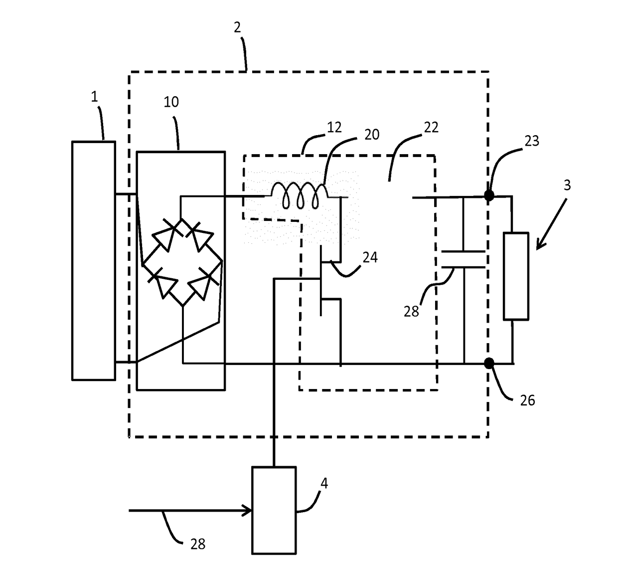
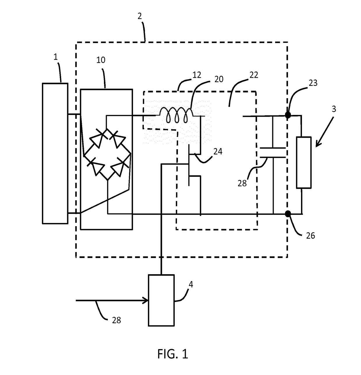
[0059]FIG. 1 shows a first example of a possible triboelectric power generator system, based on boost converter for providing impedance control.

[0060]The system comprises a triboelectric generator 1 which generates electrical power in response to movement.

[0061]The triboelectric generator is of known design, and for example generates an alternating voltage waveform with a magnitude that depends on the strength of movement. Various designs of triboelectric generator are discussed above. This invention relates in particular to the electrical processing of the signal generated by the triboelectric generator. Th...


PUM


Abstract

A triboelectric power generator system uses a power converter to provide a controllable impedance between a triboelectric power generator and a load, in dependence on the triboelectric generator output. This enables improved power transfer even though the output generated by a triboelectric power generator can be irregular and fluctuates over time.

Description

FIELD OF THE INVENTION[0001]This invention relates to a triboelectric power generation system and method.BACKGROUND OF THE INVENTION[0002]The triboelectric effect is based on contact-induced electrification in which a material becomes electrically charged after it is contacted with a different material through friction. It has been proposed to make use of this charge flow to power mobile devices such as sensors and smartphones by capturing the otherwise wasted mechanical energy from such sources as walking, the wind blowing, vibration or ocean waves. Beyond the use as a power source, the triboelectric effect has been proposed for sensing without an external power source. Because the generators produce current when they are perturbed, they can be used to measure changes in flow rates, sudden movement, or even falling raindrops.[0003]The triboelectric effect is based on a series that ranks various materials according to their tendency to gain electrons (become negatively charged) or l...

Claims


Application Information

Patent Timeline
IPC IPC(8): H02N1/04H02M7/06H02M3/156
CPCH02N1/04H02M7/06H02M3/156G05F1/656
Inventor RUTGERS, ANDREW ULRICHJOHNSON, MARK THOMASDAVIE, ALAN JAMES
Owner KONINKLJIJKE PHILIPS NV
Why Eureka
Try Eureka