Inverting control system applicable to well sites of oil fields and used for photovoltaic power generation grid connection, and work method

A photovoltaic power generation and inverter control technology, applied in photovoltaic power generation, electrical components, circuit devices, etc., can solve the problems of low motor load rate, unreasonable, low power factor of pumping units, etc., and achieve the effect of improving output power

Active Publication Date: 2015-01-28
扬州市苏油环能工程有限公司
View PDF3 Cites 5 Cited by
  • Summary
  • Abstract
  • Description
  • Claims
  • Application Information

AI Technical Summary

Problems solved by technology

The motor matching of the pumping unit has the unreasonable phenomenon of "big horses and small carts", and the pumping unit is half or empty, and the load rate of the motor is generally low, so the power factor of the pumping unit is very low when it is running, and the power loss is serious.
[0004] In the prior art, Chinese Patent No. 201120440071.5, Authorized Announcement No. CN 202309101 U, the utility model patent of "Oilfield Distributed Photovoltaic Power Generation Device" on July 4, 2014, discloses an oilfield distributed photovoltaic power generation device, It mainly uses technologies such as distributed power generation, common DC bus mu

Method used


Image

  • Inverting control system applicable to well sites of oil fields and used for photovoltaic power generation grid connection, and work method
  • Inverting control system applicable to well sites of oil fields and used for photovoltaic power generation grid connection, and work method
  • Inverting control system applicable to well sites of oil fields and used for photovoltaic power generation grid connection, and work method

Examples


Embodiment 1

[0022] For the sake of clarity, the inverter control system for grid-connected photovoltaic power generation suitable for oil field well sites may be simply referred to as an inverter control system.

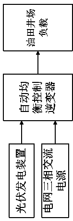
[0023] figure 1 shows the principle block of the inverter control system Figure 1 .

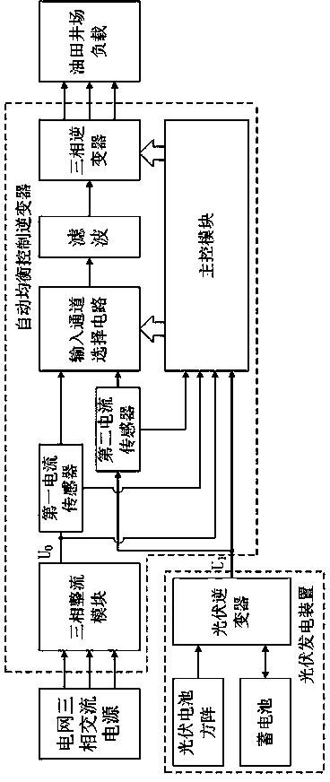
[0024] like figure 1 As shown, an inverter control system for grid-connected photovoltaic power generation suitable for oil field well sites, including: a photovoltaic power generation device, and an automatic balance control inverter connected to the grid-connected converter in the photovoltaic power generation device, said The three-phase output end of the automatic balance control inverter is connected to the oil field well site load; wherein, the automatic balance control inverter is suitable for converting the three-phase power of the connected power grid into a DC output voltage U 0 , and the DC output voltage U 0 with the DC output voltage of the grid-connected converter U 1 In com...

Embodiment 2

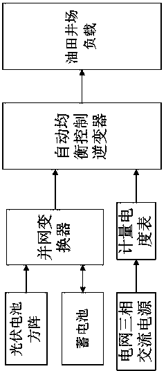
[0035] like Figure 1 to Figure 3 As shown, a working method of an inverter control system for grid-connected photovoltaic power generation based on Embodiment 1, wherein the inverter control system for grid-connected photovoltaic power generation includes: a photovoltaic power generation device, and the photovoltaic power generation device The automatic balance control inverter connected with the grid-connected converter, the three-phase output end of the automatic balance control inverter is connected with the oil field well site load. The working method includes: converting the connected grid three-phase power into a DC output voltage U through the automatic balancing control inverter 0 , and the DC output voltage U 0 with the DC output voltage of the grid-connected converter U 1 In comparison, an output voltage with a higher voltage value is selected as the input voltage of the three-phase inverter in the automatic balancing control inverter.

[0036] The automatic bala...


PUM


Abstract

The invention relates to an inverting control system applicable to well sites of oil fields and used for photovoltaic power generation grid connection, and a work method. The inverting control system comprises a photovoltaic power generation device and an automatic equalization control inverter connected with a grid connection converter which is arranged in the photovoltaic power generation device. A three-phase output end of the automatic equalization control inverter is connected with a load of a well site of an oil field. The automatic equalization control inverter is suitable to convert switched-in power grid three-phase electricity into direct-current output voltage U0, and compares the direct-current output voltage U0 with direct-current output voltage U1 of the grid connection inverter to choose the output voltage with high voltage value to serve as input voltage of a three-phase inverter of the automatic equalization control inverter. The inverting control system achieves grid connection of output electricity of the photovoltaic power generation device and mains supply as well as automatic regulation and control through the automatic equalization control inverter, ensures that the three-phase inverter obtains the optimum input voltage, and accordingly improves the output power of the three-phase inverter.

Description

technical field [0001] The invention relates to the technical field of photovoltaic power generation, in particular to an inverter control system and working method for grid-connected photovoltaic power generation suitable for oil field well sites. Background technique [0002] After the 1970s, with the development of modern industry, the global energy crisis and air pollution problems have become increasingly prominent, traditional fossil fuel energy is decreasing day by day, and the harm to the environment has become increasingly prominent. The whole world has turned its attention to renewable energy, hoping that renewable energy can change the energy structure of mankind and maintain long-term sustainable development. Among them, solar energy has become the focus of attention due to its unique advantages. Abundant solar energy is an inexhaustible, inexhaustible, pollution-free, cheap energy source that human beings can use freely. The energy of solar energy reach...

Claims


Application Information

Patent Timeline
IPC IPC(8): H02J3/38
CPCH02J3/383Y02E10/56
Inventor 魏燕丁华孙斌
Owner 扬州市苏油环能工程有限公司
Why Eureka
Try Eureka