Hybrid vehicle and control method for hybrid vehicle

a hybrid vehicle and control method technology, applied in mechanical equipment, engine-driven generator propulsion, transportation and packaging, etc., can solve the problems of driver's likely feeling of acceleration failure (a sense of torque loss), prevent a driver from feeling a sense of slowness, and reduce the increase rate of engine rotation speed

Active Publication Date: 2017-12-07
TOYOTA JIDOSHA KK +1
View PDF0 Cites 9 Cited by
  • Summary
  • Abstract
  • Description
  • Claims
  • Application Information

AI Technical Summary

Benefits of technology

[0012]In the above-described hybrid vehicle, the electronic control unit may be configured to decrease an increase rate of the rotation speed of the engine during increasing the rotation speed of the engine after motoring of the engine by the first motor ends when the target motoring rotation speed is low compared to when the target motoring rotation speed is high. The increase rate of the rotation speed of the engine may be an increase rate per unit time of the rotation speed of the engine. According to the above-described configuration, when the target motoring rotation speed is made lower, it is possible to increase torque (so-called directly transmitted torque) output to the drive shaft through the planetary gear device with torque from the engine and torque from the first motor at the time of increasing the rotation speed of the engine after motoring control ends. As a result, it is possible to prevent a driver from feeling a sense of slowness.
[0013]In the above-described hybrid vehicle, the electronic control unit may be configured to decrease an increase rate of the rotation speed of the engine during increasing the rotation speed of the engine after motoring of the engine by the first motor ends when the motoring time is short compared to when the motoring time is long. The increase rate of the rotation speed of the engine may be an increase rate per unit time of the rotation speed of the engine. According to the above-described configuration, when the target motoring rotation speed is made lower or the motoring time is made shorter, it is possible to increase torque (so-called directly transmitted torque) output to the drive shaft through the planetary gear device with torque from the engine and torque from the first motor at the time of increasing the rotation speed of the engine after motoring control ends. As a result, it is possible to prevent a driver from feeling a sense of slowness.

Problems solved by technology

If this state is continued for a comparatively long time, a driver is likely to feel a sense of failure in acceleration (a sense of torque loss).

Method used


Image

  • Hybrid vehicle and control method for hybrid vehicle
  • Hybrid vehicle and control method for hybrid vehicle
  • Hybrid vehicle and control method for hybrid vehicle

Examples


Embodiment Construction

[0033]Next, a mode for carrying out the disclosure will be described in connection with an example.

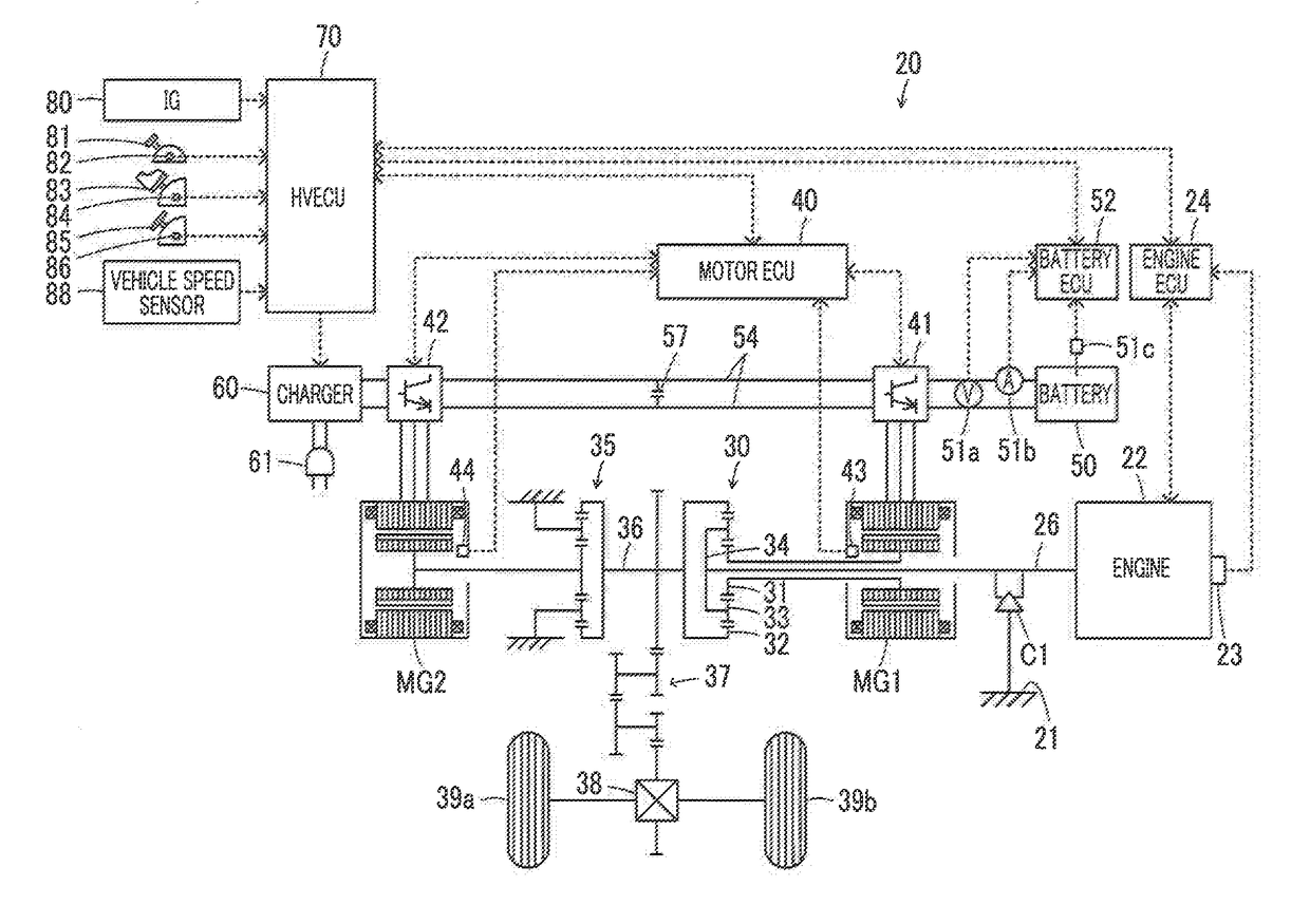
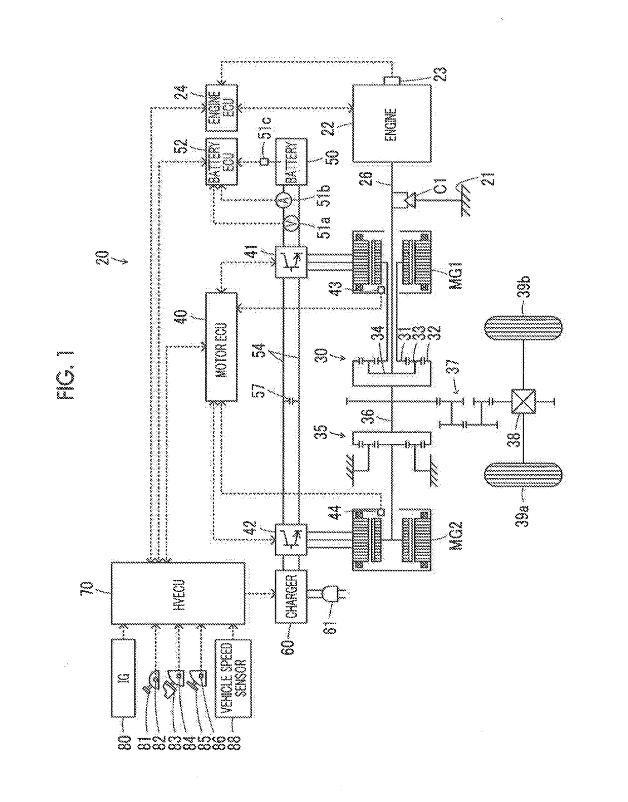
[0034]FIG. 1 is a configuration diagram showing the outline of the configuration of a hybrid vehicle 20 as an example of the disclosure. As shown in FIG. 1, the hybrid vehicle 20 of the example includes an engine 22, a planetary gear 30 as a planetary gear device, a one-way clutch C1, motors MG1, MG2, inverters 41, 42, a battery 50, a charger 60, and a hybrid electronic control unit (hereinafter, referred to as an “HVECU”) 70.

[0035]The engine 22 is constituted as an internal combustion engine which outputs power with gasoline, diesel, or the like as fuel. The engine 22 is operated and controlled by an engine electronic control unit (hereinafter, referred to as an “engine ECU”) 24.

[0036]Though not shown, the engine ECU 24 is constituted as a microcomputer centering on a CPU, and includes, in addition to the CPU, a ROM which stores a processing program, a RAM which temporarily stores dat...


PUM


Abstract

When an output limitation value of a battery is equal to or less than a threshold, an electronic control unit determines that basic torque is able to be output from a second motor to a drive shaft. Then, the electronic control unit sets a predetermined value as a target motoring rotation speed for ending motoring of an engine by a first motor. When the output limitation value is greater than the threshold, the electronic control unit determines that the basic torque is unable to be output from the second motor to the drive shaft at the time of starting the engine, and sets a value smaller than the predetermined value as the target motoring rotation speed.

Description

INCORPORATION BY REFERENCE[0001]The disclosure of Japanese Patent Application No. 2016-111731 filed on Jun. 3, 2016 including the specification, drawings and abstract is incorporated herein by reference in its entirety.BACKGROUND1. Technical Field[0002]The present disclosure relates to a hybrid vehicle and a control method for a hybrid vehicle.2. Description of Related Art[0003]A hybrid vehicle in which a motor generator is connected to a sun gear of a planetary gear, an engine is connected to a carrier of a planetary gear, and a drive shaft is connected to a ring gear of a planetary gear, a propulsion motor is connected to the drive shaft, and a one-way clutch configured to inhibit reverse rotation (negative rotation) of the engine is provided has been suggested (for example, see Japanese Patent Application Publication No. 2003-201880 (JP 2003-201880 A)). In this hybrid vehicle, when a maximum acceleration is required and estimated total torque of the propulsion motor and the motor...

Claims


Application Information

Patent Timeline
Patent Type & Authority Applications(United States)
IPC IPC(8): B60W10/08B60K6/445B60W10/06B60L50/16
CPCB60W10/08B60W10/06B60K6/445B60L2240/423B60W2520/10B60W2510/083B60W2510/244B60W2540/10B60L2240/486B60W20/10B60W2710/0644B60K6/365B60K6/383B60W2510/085B60W2510/246B60W2710/083B60W20/40B60W20/19B60W10/26B60W2710/248Y02T10/40Y02T10/62Y02T10/72B60K6/48B60K2006/266B60W20/00
Inventor HOKOI, KOJIYOSHIHARA, KOJIINAOKA, KOTAROYAMAMOTO, KOJI
Owner TOYOTA JIDOSHA KK
Why Eureka
Try Eureka