Production method of ball screw device and production method of steering system using ball screw device

a production method and technology of a ball screw device, which are applied in mechanical equipment, transportation and packaging, and production methods of the respective components. the effect of low production cos

Active Publication Date: 2017-12-07
JTEKT CORP
View PDF3 Cites 3 Cited by
  • Summary
  • Abstract
  • Description
  • Claims
  • Application Information

AI Technical Summary

Benefits of technology

[0007]An object of the present invention is to provide a production method of a ball screw device at low production cost and a production method of a steering system using the ball screw device.

Problems solved by technology

However, when this clearance exceeds a certain value, a vibration, for example, during operation of the ball screw device may cause (inner surfaces of) the respective ball grooves to hit the rolling balls after moving by an amount corresponding to the clearance and generate a loud hitting noise (rattle noise).
However, producing the respective components with high accuracy has limitations and causes cost increase.
In general, the originally assembled rolling balls are all discarded because it is difficult to perform quality assurance thereon.
These processes require much time and many components, which may cause significant cost increase.

Method used


Image

  • Production method of ball screw device and production method of steering system using ball screw device
  • Production method of ball screw device and production method of steering system using ball screw device
  • Production method of ball screw device and production method of steering system using ball screw device

Examples


first embodiment

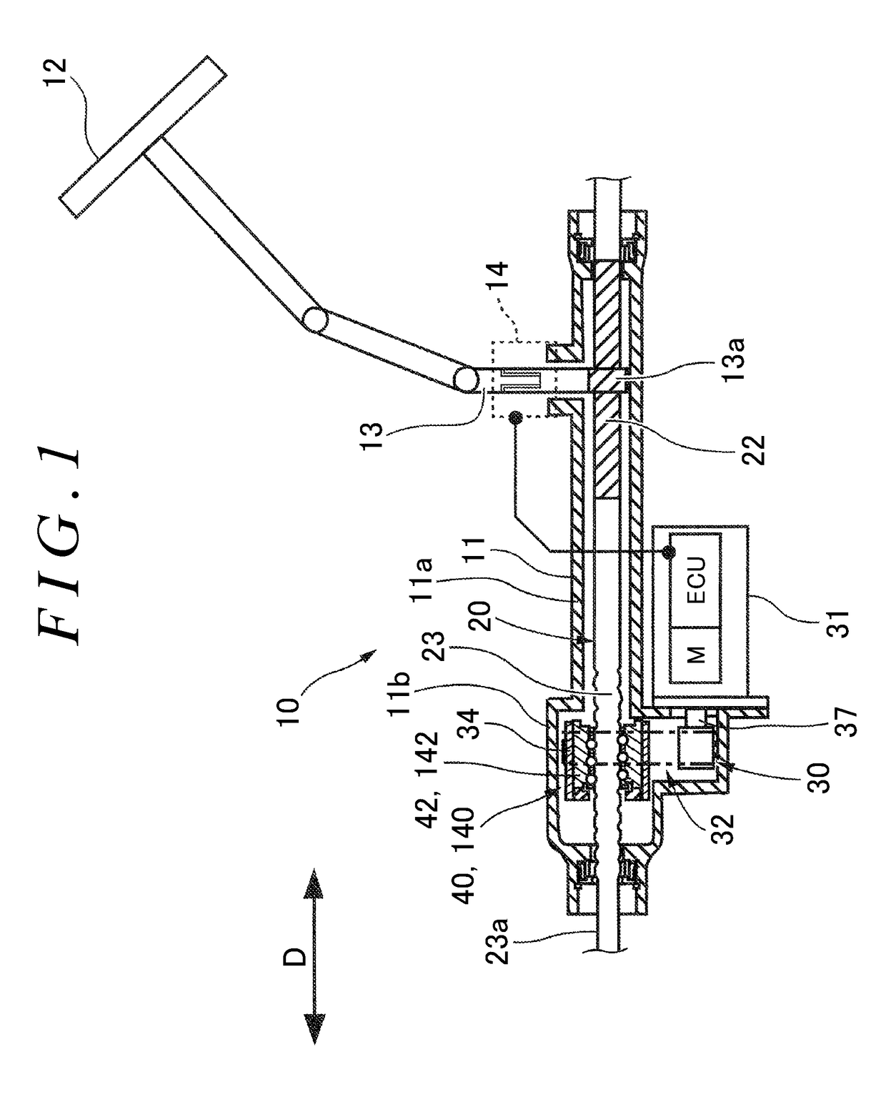
[0021]the present invention will now be described with reference to the drawings. FIG. 1 is a diagram of an entire configuration of an electric power steering system (corresponding to a steering system) of a vehicle, in which a mode is exemplified in which a ball screw device produced by a production method according to the present invention is used in the electric power steering system.

[0022]The electric power steering system is a steering system that assists steering force with steering assist force. The ball screw device of the present invention may be used in various systems in which the ball screw device can be used, such as a four-wheel steering system, a rear-wheel steering system, a steer-by-wire steering system in addition to the electric power steering system.

[0023]This electric power steering system 10 (hereinafter, simply called “steering system 10”) is a system that changes the orientation of steered wheels (not depicted) of a vehicle by moving a steering operation shaf...

second embodiment

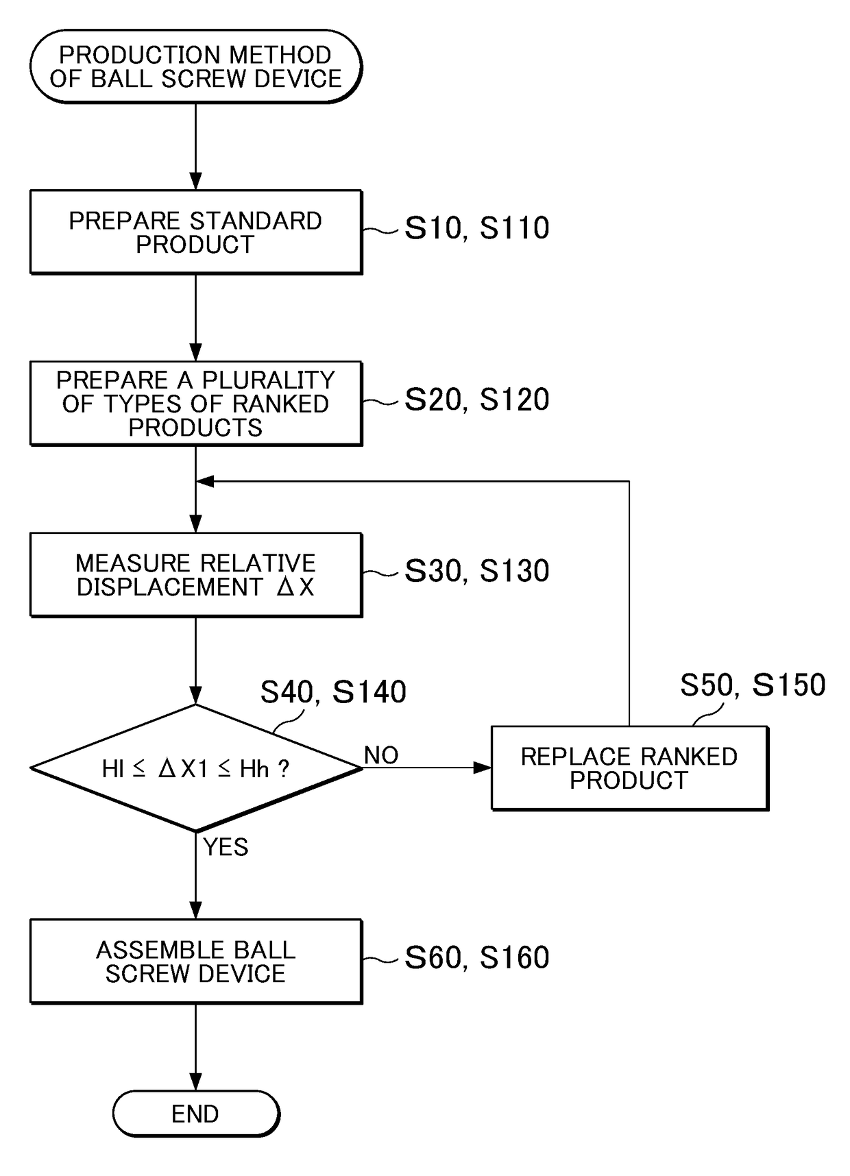
[0082]As the modification 2 of the second embodiment, at the second preparation step S120, a plurality of master bodies (not depicted) of ball screw shafts 120, to each of which an ordinary nut S / A can be assembled, may be prepared in advance, and ordinary nut S / As may be each assembled to these master bodies. The relative displacement ΔX1 may be then measured, and based on the measurement results of the relative displacement ΔX1, the nut S / As 141 as ranked products may be sorted to be prepared. Herein, criteria for the relative displacement ΔX1 in sorting the nut S / As 141 may be optionally determined. The master bodies of the ball screw shafts 120 are produced such that the outer pitch circle diameters φDpw1 of the ball screw shafts 120 match a plurality of third master values φDm1 within the range of the dimensional specification.

[0083]The following describes advantageous effects of the respective embodiments. According to the first embodiment and the modification 1, in the produc...


PUM


Abstract

A production method of a ball screw device is provided. The ball screw device includes a ball screw portion, a ball nut, rolling balls, and a retainer. The production method of the ball screw device includes: a first preparation step of preparing a nut subassembly as a standard product; a second preparation step of preparing the ball screw portion in plurality by types as ranked products; a measuring step of measuring a relative displacement in a thrust direction between the standard product and each ranked product; a determination step of determining whether the displacement meets a displacement specification; a replacing step of, if the displacement does not meet the specification, replacing the ranked product with another ranked product; and an assembling step of, if the displacement meets the specification, assembling the standard product and the ranked product into the ball screw device.

Description

INCORPORATION BY REFERENCE[0001]The disclosure of Japanese Patent Application No. 2016-110460 filed on Jun. 1, 2016 including the specification, drawings and abstract, is incorporated herein by reference in its entirety.BACKGROUND OF THE INVENTION1. Field of the Invention[0002]The present invention relates to a production method of a ball screw device and a production method of a steering system using the ball screw device.2. Description of Related Art[0003]Conventionally, ball screw device as described in Japanese Patent No. 5120040 (JP 5120040), Japanese Utility Model Application Publication No. 2-5145, and Japanese Patent Application Publication No. 6-288458 (JP 6-288458 A) have been used. These ball screw device each include a ball screw shaft having a ball groove formed on its outer periphery, a ball nut disposed on the outer peripheral side of the ball screw shaft and having a ball groove formed on its inner periphery, and a plurality of rolling balls that are retained in a ro...

Claims


Application Information

Patent Timeline
Patent Type & Authority Applications(United States)
IPC IPC(8): F16H25/22B62D3/08B62D5/04
CPCF16H25/2233B62D5/0424B62D5/0448B62D3/08B62D3/02B62D5/04F16H25/2204F16H2025/2481B62D5/00
Inventor ASAKURA, TOSHIHIRONAKAYAMA, TAKUYAOGAWA, KEISUKE
Owner JTEKT CORP
Why Eureka
Try Eureka