
Impact absorbing matting and padding system with elastomeric sub-surface structure

a technology of elastomeric sub-surface structure and impact absorption, which is applied in the direction of shock absorption, elastic dampers, sport apparatuses, etc., can solve the problems of many problems of most conventional impact absorption system, the least available cushioning capacity the hardness of conventional impact absorption structure, etc., to achieve stable work surface, and easy deformation or compression

Active Publication Date: 2017-12-14
BETTERIDGE BRYCE L +1
View PDF3 Cites 5 Cited by
  • Summary
  • Abstract
  • Description
  • Claims
  • Application Information

AI Technical Summary

Benefits of technology

The patent describes a system of elastomeric structures that can be used beneath a surface layer for anti-fatigue matting and in athletic equipment and shoes. The structures are designed to absorb impact and protect against bottoming out. When used in a mat, they provide stability and cushioning while still reducing foot entrapment effects. The system also provides a more stable surface layer that allows for flexing and recovery after being walked on or impacted. Overall, the patent presents a solution for creating a safe and effective surface for athletic activity.

Problems solved by technology

The problems with most conventional matting systems are many.
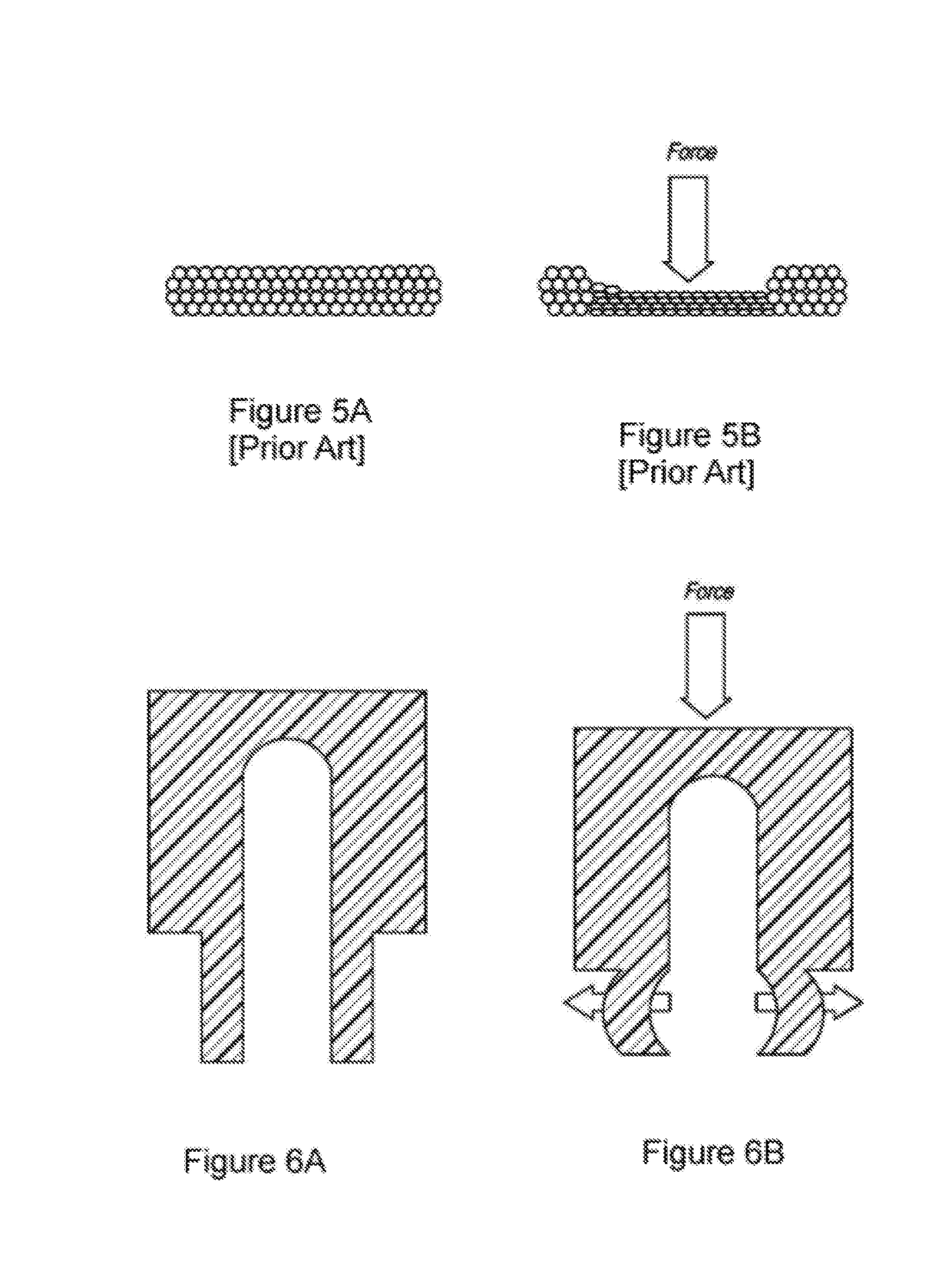
Most conventional impact attenuating structures get harder as the force applied to them increases.
Their cushioning capability is therefore least available when it is most needed.
Foam mats particularly compress to a hardness that does not provide adequate support or cushioning.
In addition, foam materials can easily bottom out, allowing potentially injurious impact right through the mat and onto the harder floor surface beneath.
A surface that is slow to respond when pressure is released will be partially compressed as a load is repeatedly placed on it, and any positive effect of the cushioning will be lost.
Conventional systems tend to compact with time, thus leading to both localized and generalized compaction and hardening of the energy absorption layer.
However, the mats are seldom increased in thickness to compensate for the addition of dense rubber, and therefore it reduces the amount of the more impact-absorbing material for a given height of mat.
Dense forms of rubber do not provide bottoming-out protection and are relatively incompressible providing little anti-fatigue benefit.
Too soft and a mat may actually increase fatigue (imagine standing and working on a mattress).
In addition, when a mat is too soft, the instablilty will require an unwarranted amount of muscular activity as the body works to retain balance.
This will actually accelerate muscular fatigue, and all its accompanying ills, such as back, hip, knee, ankle and foot pain.
However, a mat that is too hard, or that bottoms out easily with normal standing and moving weight, will not be appreciatively better than standing on no mat at all.
In addition, in most conventional systems, the force absorbing mechanism begins with an immediate displacement at the very surface of the mat, a displacement that often leads to dangerous foot entrapment and / or other displacement instability for those who play, walk or work on such a surface.
This leads to additional fatigue as the worker is constantly, if subtly, walking uphill with each foot movement.
Closed cell foam systems, especially, provide dangerous surface deformation levels that often lead to foot lock or foot entrapment on surfaces having a foam substructure.
Even if the worker does not slip or trip, dealing with the uneven surface causes additional fatigue.
In working situations, where the height of a work surface is standardized, the thickness of anti-fatigue matting is problematic.
While mat heights of 25 to 75 mm were at one time considered optimal, that has changed, and a demand for thinner mats has impacted the market.
However, as a need has developed in recent years for ever smaller cells in thinner materials, it became evident to us that our previous formulations in cell shapes, dimensions, and height ratios (of more compressible to less compressible regions) would not result in impact absorbing material that could perform at comparable levels with our previous innovations.
However, there has been considerable controversy as to the benefits of cushioning in athletic footwear over the last decade.
All of these systems exhibit the difficulties of any padding system, many of which have been dismissed above.
Foam, gels and liquid tend to be heavy.
Other elastomeric structures get harder as the force applied to them increases, and also bottom out suddenly when the tube, wave or bellows flattens.
In addition, problems arise because, discussed above, these systems must balance cushioning with stability.
However, this additional muscular training is at the expense of performance.
As with the mats discussed above, most pads used in sports equipment and sports shoes are designed such that they begin with an immediate displacement at the surface of impact, causing dangerous and directionally-unpredictable deformation.

Method used


Image

  • Impact absorbing matting and padding system with elastomeric sub-surface structure
  • Impact absorbing matting and padding system with elastomeric sub-surface structure
  • Impact absorbing matting and padding system with elastomeric sub-surface structure

Examples


Embodiment Construction

[0043]Turning now to the drawings, the invention will be described in a preferred embodiment by reference to the numerals of the drawing figures wherein like numbers indicate like parts.

[0044]Reference throughout this specification to “one embodiment” or “an embodiment” means that a particular feature, structure, or characteristic described in connection with the embodiment is included in at least one embodiment of the invention. Thus, the appearances of the phrases “in one embodiment” or “in an embodiment” in various places throughout this specification are not necessarily all referring to the same embodiment. Furthermore, the particular features, structures, or characteristics may be combined in any suitable manner in one or more embodiments.

[0045]Reference throughout this specification to a “column” refers to a tubular shafted support structure, typically having a cylindrical of polygonal abaft and two shaft ends. Similarly, references throughout this specification to a “cylinder...


PUM

PropertyMeasurementUnit
Fractionaaaaaaaaaa
Fractionaaaaaaaaaa
Angleaaaaaaaaaa

Abstract

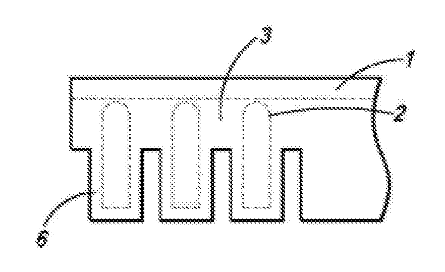
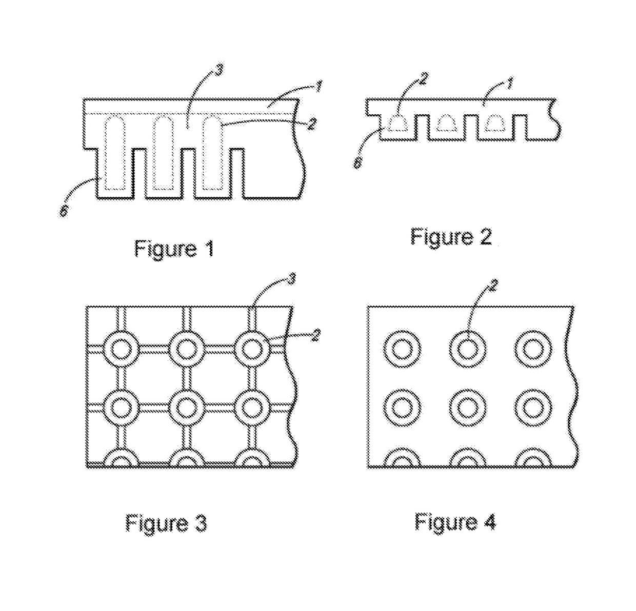
A cushioning and impact absorbing pad with a surface layer of thickness t, and an elastomeric sub-surface-structure of height h. The sub-surface structure comprises an array of elastomeric columns wherein each column has a frustoconical column wall surrounding a central void. The frustoconical column walls have a zone that is a more compressible, relatively collapsible zone in a region at an end of the column opposite the surface layer and a zone that is a relatively less compressible zone in a region at the end of the column abutting the surface layer. Column walls are tapered with draft angles in the range of greater than 6 degrees and less than 10 degrees.

Description

[0001]This application claims priority to U.S. Provisional Patent Application 62 / 348,117 files Jun. 9, 2016 and is hereby incorporated as if fully set forth herein.TECHNICAL HELD[0002]The invention relates to systems for attenuating applied force and absorbing impact energy; more particularly, it relates to anti-fatigue and stabilizing padding with elastomeric subsurface structures for attenuating applied force and absorbing impact energy; more particularly it relates to impact absorbing, anti-fatigue matting systems and impact absorbing, stabilizing padding with elastomeric subsurface structures and deformable structures for attenuating applied force and absorbing impact energy for use on surfaces in healthcare, recreation, industry and home, and as padding in sports equipment, footwear and body padding.BACKGROUND OF THE INVENTION[0003]Conventionally, some kind of matting system is used to relieve standing stress and fatigue or to attenuate impact stress. Many such systems are know...

Claims


Application Information

Patent Timeline
IPC IPC(8): F16F7/12B32B3/30F16F1/376A41D13/015A43B13/18A63B71/08
CPCF16F7/121F16F1/376B32B3/30A41D13/0156B32B2571/00A43B13/181B32B2307/56B32B2437/00A63B71/08A43B7/14A43B13/187A41D31/28B32B2471/04B32B3/08B32B3/26B32B25/042B32B2250/02B32B2250/248B32B2307/558A47G27/0231
Inventor BETTERIDGE, BRYCE L.BISHOP, ROBERT SAMUEL
Owner BETTERIDGE BRYCE L
Learn More