Surgical multi-tool and method of use

a multi-tool and surgical technology, applied in the field of medical devices, can solve the problems of limited use of surgical tools, limited use of surgical hand tools, and inability to cut all tissues, etc., to achieve convenient interchange by users, improve usability and efficiency, and limit the potential for injury

Active Publication Date: 2017-12-21
DIVYZE INC
View PDF7 Cites 5 Cited by
  • Summary
  • Abstract
  • Description
  • Claims
  • Application Information

AI Technical Summary

Benefits of technology

[0011]The surgical tool or hand tool can be used in surgical sites with limited lateral access and substantial depth. The multiple configurations can allow for tissue dissection by cutting and electrocautery. The interchangeability of the hand tool limits the number of times the hand tool would need to be removed, exchanged, and re-inserted into the surgical site. The interchangeability can limit the potential for injury, while improving usability and efficiency.
[0012]The surgical tool or hand tool of certain embodiments advantageously provides multiple functional configurations that are easily interchanged by the user. The hand tool is capable of use in open microsurgery, minimally invasive surgery, and other surgical environments. The hand tool may be a single handheld device, which allows the interchangeability of configurations without the user removing the device from the local surgical field.

Problems solved by technology

Each surgical tool has limitations.
For instance, in relation to electrosurgical devices, the passage of current through the tissue does not allow cutting of all tissues.
This limitation is pronounced when the distance between the two contact points of the device is increased.

Method used


Image

  • Surgical multi-tool and method of use
  • Surgical multi-tool and method of use
  • Surgical multi-tool and method of use

Examples


Embodiment Construction

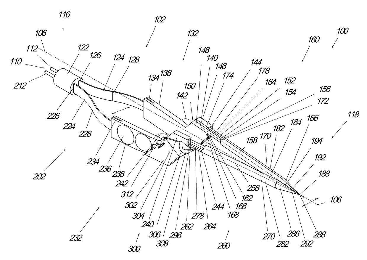
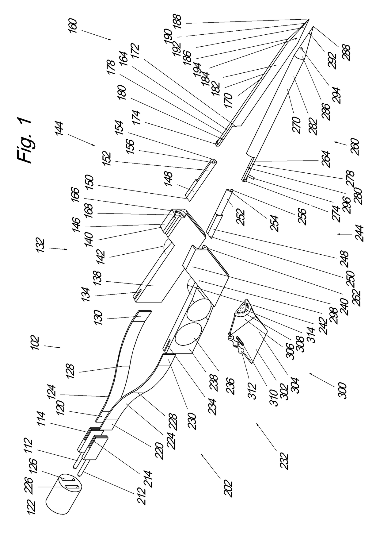
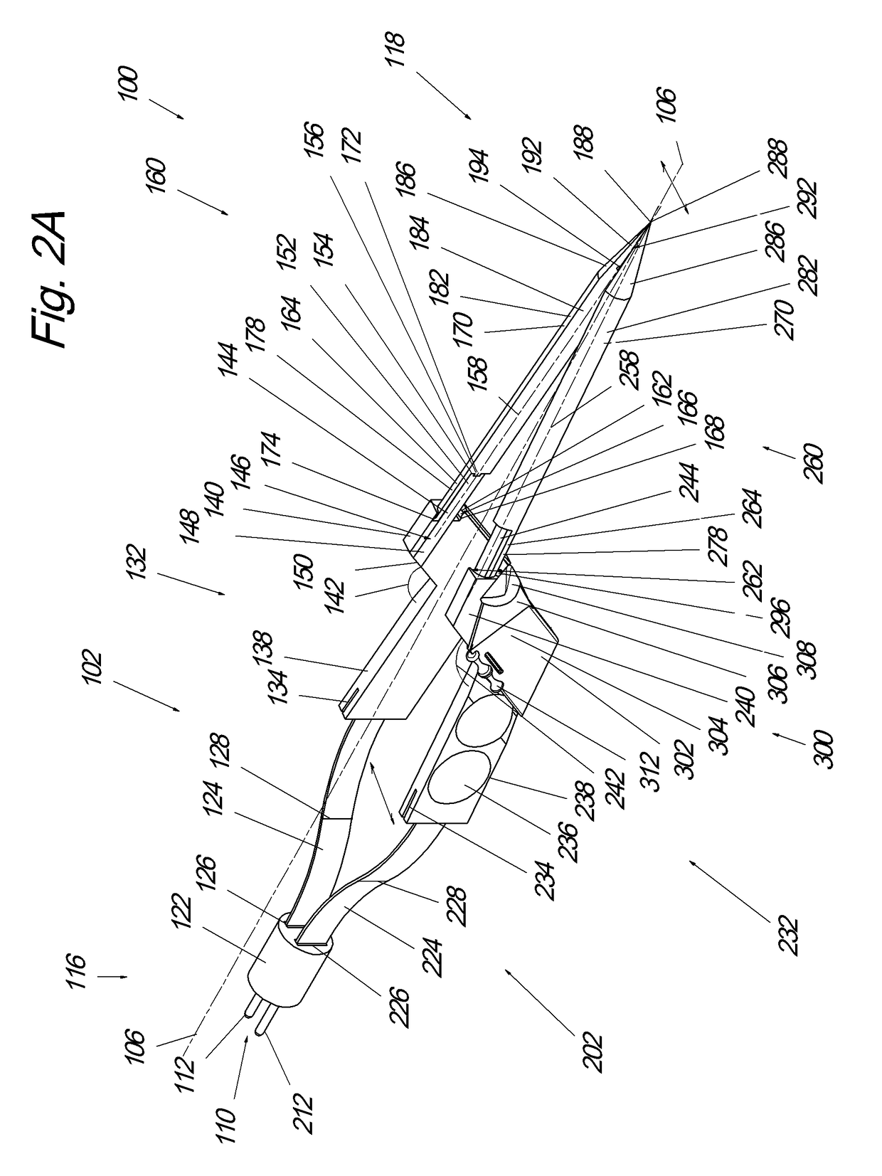
[0043]Preferred embodiments of the surgical hand tool include two sections used together to perform a function. One or more of the sections can comprise segments, portions, components, or subcomponents. However, the use of the term “section” does not imply any particular structure or configuration. In some embodiments, the right section or components thereof are mirror image, identical, or substantially similar to the left section or components thereof. The sections or components thereof may be any suitable shape that permits the function of the hand tool, for instance perform the function of scissors, forceps, and probe. Certain embodiments are illustrated and / or described herein.

[0044]With reference to FIGS. 1-2A, a hand tool 100 is shown. The hand tool 100 can also be referred to as a surgical multi-tool. The hand tool 100 comprises two sections: a left section 102 and a right section 202. In the illustrated configuration, the left section 102 includes multiple components and the...


PUM


Abstract

Surgical tool are disclosed that include a first tip and a second tip. The first tip and the second tip can have a first configuration, an intermediate configuration, and a second configuration. In the first configuration the tool operates as forceps and in the second configuration the tool operates as scissors. In the intermediate configuration the tool operates as a probe. The tips can be brought together to transition between the first configuration and the intermediate configuration. The tips can be rotated to transition between the intermediate configuration and the second configuration. Method are disclosed that include the step of providing a tool having a first tip extending distally and a second tip extending distally, moving at least one of the first tip and the second tip toward the other of the first tip and the second tip, and rotating the first tip and the second tip.

Description

INCORPORATION BY REFERENCE TO ANY PRIORITY APPLICATIONS[0001]The present application claims priority benefit under 35 U.S.C. §119(e) of U.S. Provisional Patent Application No. 62 / 352693 filed Jun. 21, 2016 and U.S. Provisional Patent Application No. 62 / 437444, filed Dec. 21, 2016, the disclosures of each are incorporated by reference herein in their entirety. Further details regarding apparatuses and methods that may be utilized or incorporated with the embodiments described herein are found in U.S. Pat. No. 9,050,101, issued Jun. 9, 2015 and U.S. Provisional Application No. 61 / 906,337 filed November 19, 2013, the entireties of which are hereby incorporated by reference.BACKGROUND OF THE INVENTIONField of the Invention[0002]The present application relates to the field of medical devices, and encompasses apparatuses for use during surgery and surgical methods. In particular, the application relates to surgical hand tools having a plurality of configurations including a forceps config...

Claims


Application Information

Patent Timeline
Patent Type & Authority Applications(United States)
IPC IPC(8): A61B17/3201A61B17/30A61B18/14A61B18/12A61B17/00
CPCA61B17/3201A61B18/1206A61B18/1445A61B2018/1457A61B17/30A61B2017/00473A61B18/1442A61B2017/00353A61B2017/00738A61B2017/2923A61B2017/305A61B2017/3454A61B2018/00577A61B2018/00595A61B2018/00601A61B2018/1455A61B2018/1462
Inventor SMITH, RYAN D.
Owner DIVYZE INC
Why Eureka
Try Eureka