

Method for producing a ceramic fixed partial denture
a technology of ceramic fixed dentures and ceramics, applied in the direction of fastening prostheses, dental prostheses, artificial teeth, etc., can solve the problems of metal use, metal allergy, dark margins, etc., and achieve the effect of improving the fit and reducing the risk of metal allergy
- Summary
- Abstract
- Description
- Claims
- Application Information
AI Technical Summary
Benefits of technology
Problems solved by technology
Method used
Image

Examples
example 1
Materials and Methods
[0053]174 specimens were used in this study and they were divided according to the adhesive used:
[0054]Group R, RelyX Unicem 2 Clicker (control);
[0055]Group M, Multilink Automix;
[0056]Group V, VITA VM9;
[0057]Group G, VITA In-Ceram ZR (infusion glass);
[0058]Group AG, infusion glass 30% and Al2O3 70%;
[0059]Group F, frit (infusion glass 90% and B2O3 10%);
[0060]Group C, colloidal zirconia; and
[0061]Group MZ, mullite zirconia.
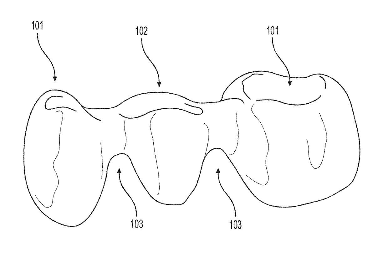
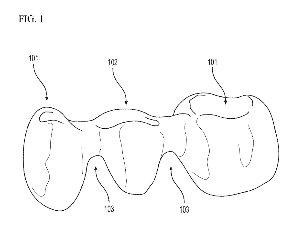
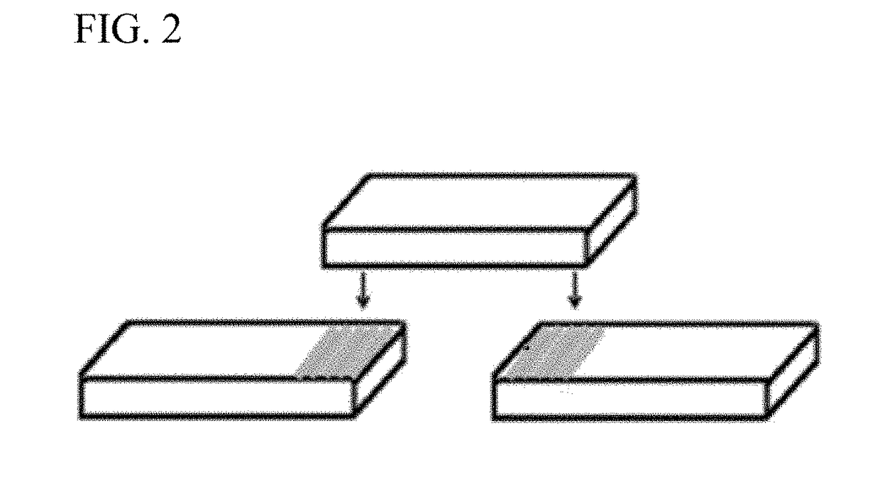
[0062]A specimen consisted of three ZrO2 bars bonded or fused together. The adhesives used to join the bars covered a surface area of 3×4 mm2. This surface area was determined with a line marked with a pencil placed 3 mm from the edges of the left and right bars and 3 mm from both edges of the middle bar (FIG. 2). Referring to FIG. 3, the solid arrow points to the pontic, the dotted arrows point to the retainers, and the double arrows point to where the sectioning would take place and the sections rejoined using the adhesives. These bars were fa...
example 2 bonding procedures
[0065]RelyX Unicem 2 clicker, a dual-curing, self-adhesive resin cement, was used to prepare the Group R specimens. Group R was divided into two subgroups: the first group (RA) was as-sintered with no surface treatment and the second group (RSb) was abrasively blasted. The cement consists of a base and a catalyst. Both components are in the form of a paste and were simultaneously extruded onto a mixing pad, and mixed for 20 seconds with a plastic spatula. The mixing ratio, based on volume, was 1:1. A customized fixture was made to hold the bars in place for curing. A weight of 100 g was placed while the cement was being cured by light. The initial curing time was 1 to 2 seconds. After which, excess cement was removed, then each surface was cured for an additional 20 seconds.
[0066]In group Ram, Monobond was used with RelyX Unicem 2 clicker to determine the effect of Monobond on another self-adhesive resin cement. The binding and curing procedures were similar to those of group R.
[006...
example 3
Sintering Procedures
[0069]Groups V, G, F, AG, C and MZ, consisted of materials that were sintered in a Vacumat 200 furnace (VITA Zahnfabrik). Each of these groups was used in different experiments with various sintering parameters: some with surface treatments (e.g. abrasive blasting) and others that had a weight on the specimens while being sintered. Materials used to bond the ZrO2 bars were mixed with deionized water using a small plastic spatula, and then the mix was placed on the two bars at the areas that are assumed to fuse with the third bar to be connected together. The specimens were then placed on a firing tray and sintered.
[0070]Group V specimens used VITA VM9 and were divided into 5 subgroups (V1-V5), where the specimens were sintered at different end temperatures for different durations at the end temperature and in vacuum. Group V1 specimens were sintered to 950° C., held for 5 minutes with 10 minutes of vacuum. Group V2 specimens were sintered to 980° C., held for 1 m...
PUM
| Property | Measurement | Unit |
|---|---|---|
| Temperature | aaaaa | aaaaa |
| Temperature | aaaaa | aaaaa |
| Temperature | aaaaa | aaaaa |
Abstract
Description
Claims
Application Information