Transdermal absorption sheet
- Summary
- Abstract
- Description
- Claims
- Application Information
AI Technical Summary
Benefits of technology
Problems solved by technology
Method used
Image
Examples
example 1
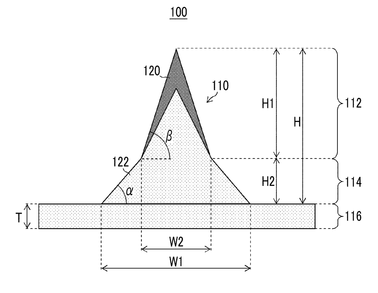
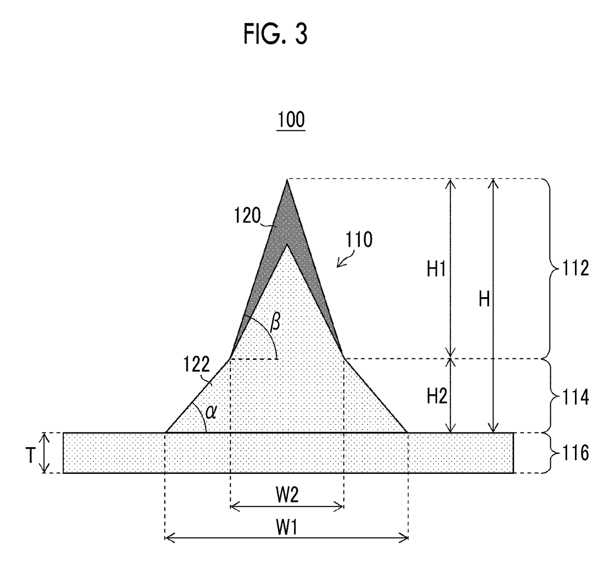
[0234](Production of Mold) An original plate 11 was produced by subjecting protruding portions 12 each with a needle-like structure to grinding at a pitch L of 1,000 μm in a two-dimensional array with 10 columns and 10 rows on the surface of a smooth Ni plate having one side of 40 mm. As shown in FIGS. 30A and 30B, each protruding portion 12 with a needle-like structure includes a truncated cone 12A with a circular bottom surface having a diameter D1 of 500 μm and a height H1 of 150 μm, and a cone 12B formed on the truncated cone 12A and having a circular bottom surface having a diameter D2 of 300 μm and a height H2 of 500 μm. On the original plate 11, a film with a thickness of 0.6 mm was formed using a silicone rubber (SILASTIC (registered trademark) MDX4-4210, manufactured by Dow Coming Corporation) as a material. The film was thermally cured in a state in which the conical tip end portions of the original plate 11 were projected by 50 μm from the film surface, and then the therm...
example 2
[0255]The same preparation of a polymer solution containing a drug, preparation of a polymer solution not containing a drug, drug solution filling step, drug solution drying step, peeling-off step, and final drying step as in Example 1 were performed except that the base solution filling step and the base solution drying step performed in Example 1 were changed as follows.
[0256](Base Solution Filling Step and Base Solution Drying Step)
[0257]A thin stainless steel plate having an opening portion with a diameter of 16 mm and a thickness of 500 μm was prepared as a form. The mold filled with the drug solution was fixed to the suction apparatus by suction. The position of the needle-like recessed portion region of the mold was aligned to be in the opening portion of the thin stainless steel plate, and the thin stainless steel plate was superposed on the surface of the mold. The base solution was poured into the opening portion of the thin stainless steel plate and an excessive amount of...
example 3
[0266]The same preparation of a polymer solution containing a drug, preparation of a polymer solution not containing a drug, drug solution filling step, drug solution drying step, peeling-off step, and final drying step as in Example 1 were performed except that the base solution filling step and the base solution drying step performed in Example 1 were changed as follows.
[0267](Base Solution Filling Step and Base Solution Drying Step)
[0268]A thin stainless steel plate having an opening portion with a diameter of 16 mm and a thickness of 200 μm was prepared as a form. The mold filled with the drug solution was fixed to the suction apparatus by suction. The position of the needle-like recessed portion region of the mold was aligned to be in the opening portion of the thin stainless steel plate, and the thin stainless steel plate was superposed on the surface of the mold. The base solution was poured into the opening portion of the thin stainless steel plate and an excessive amount of...
PUM
| Property | Measurement | Unit |
|---|---|---|
| Thickness | aaaaa | aaaaa |
| Thickness | aaaaa | aaaaa |
| Thickness | aaaaa | aaaaa |
Abstract
Description
Claims
Application Information
 - R&D
- Intellectual Property
- Life Sciences
- Materials
- Tech Scout
- Unparalleled Data Quality
- Higher Quality Content
- 60% Fewer Hallucinations
Browse by: Latest US Patents, China's latest patents, Technical Efficacy Thesaurus, Application Domain, Technology Topic, Popular Technical Reports.
© 2025 PatSnap. All rights reserved.Legal|Privacy policy|Modern Slavery Act Transparency Statement|Sitemap|About US| Contact US: help@patsnap.com


