System and Method For Rotational Position Tracking Of Brake Lathe Adjustment Assembly

a technology of rotational position tracking and brake rotor adjustment, which is applied in the field of system and method for rotational position tracking of brake rotor adjustment assembly and on-board brake rotor apparatus, can solve the problems of lateral warping frequent and substantial frictional force on the rotor, and formation of grooves, channels or scratches on the surface of the brake rotor, so as to reduce the time required

Active Publication Date: 2017-12-21
HUNTER ENG
View PDF0 Cites 6 Cited by
  • Summary
  • Abstract
  • Description
  • Claims
  • Application Information

AI Technical Summary

Benefits of technology

[0015]It is further desirable to create a brake resurfacing system that will detect when a rotor resurfacing cut is completed and automatically stop the operation of the brake lathe, thereby reducing the time required for the operator to prepare the brake lathe to resurface the next rotor.

Problems solved by technology

The brake rotors are subjected to frequent and substantial frictional forces by the brake friction pads, and over time, become worn.
Uneven application of braking force, debris, or uneven frictional surfaces on the brake friction pads can result in the formation of grooves, channels, or scratches in the surfaces of the brake rotors.
Repeated heating and cooling of the brake rotors resulting in extreme temperature variations can additionally result in a lateral warping of the brake rotors.
However, once a brake rotor has been worn below a minimum safe thickness, it is unable to safely dissipate the heat generated during brake application, and must be replaced.
Additional sources of lateral warping defects in a brake rotor include over tightened attachment bolts or uneven mounting surface onto which the brake rotor is secured in the vehicle wheel assembly.
If the brake rotor is removed from the vehicle wheel assembly for a resurfacing operation on a fixed or “bench” brake lathe, any abnormalities or defects resulting from the mounting of the brake rotor to the vehicle wheel assembly may not be accurately identified or corrected during the resurfacing procedure.
Some manual runout compensation procedures are tedious and complex.
The extra time spent by an operator to setup the on-car brake lathe and perform the manual runout compensation can substantially increase the time required to complete a brake rotor resurfacing, resulting in a corresponding increase in cost and lost productivity.
Due to significant high speed vibrations and the interaction of the various rotating components, such as bearings, gears, and shaft, errors are induced in the automatic runout compensation sensor signals.
The automated adjustment mechanism of the '911 Newell et al. patent associated with the use of the one or more slant rotors is a costly and complex mechanical arrangement.

Method used


Image

  • System and Method For Rotational Position Tracking Of Brake Lathe Adjustment Assembly
  • System and Method For Rotational Position Tracking Of Brake Lathe Adjustment Assembly
  • System and Method For Rotational Position Tracking Of Brake Lathe Adjustment Assembly

Examples


Embodiment Construction

[0034]The following detailed description sets forth the invention by way of example and not by way of limitation. The description enables one skilled in the art to make and use the present disclosure, and describes several embodiments, adaptations, variations, alternatives, and uses of the present disclosure, including what is presently believed to be the best mode of carrying out the invention.

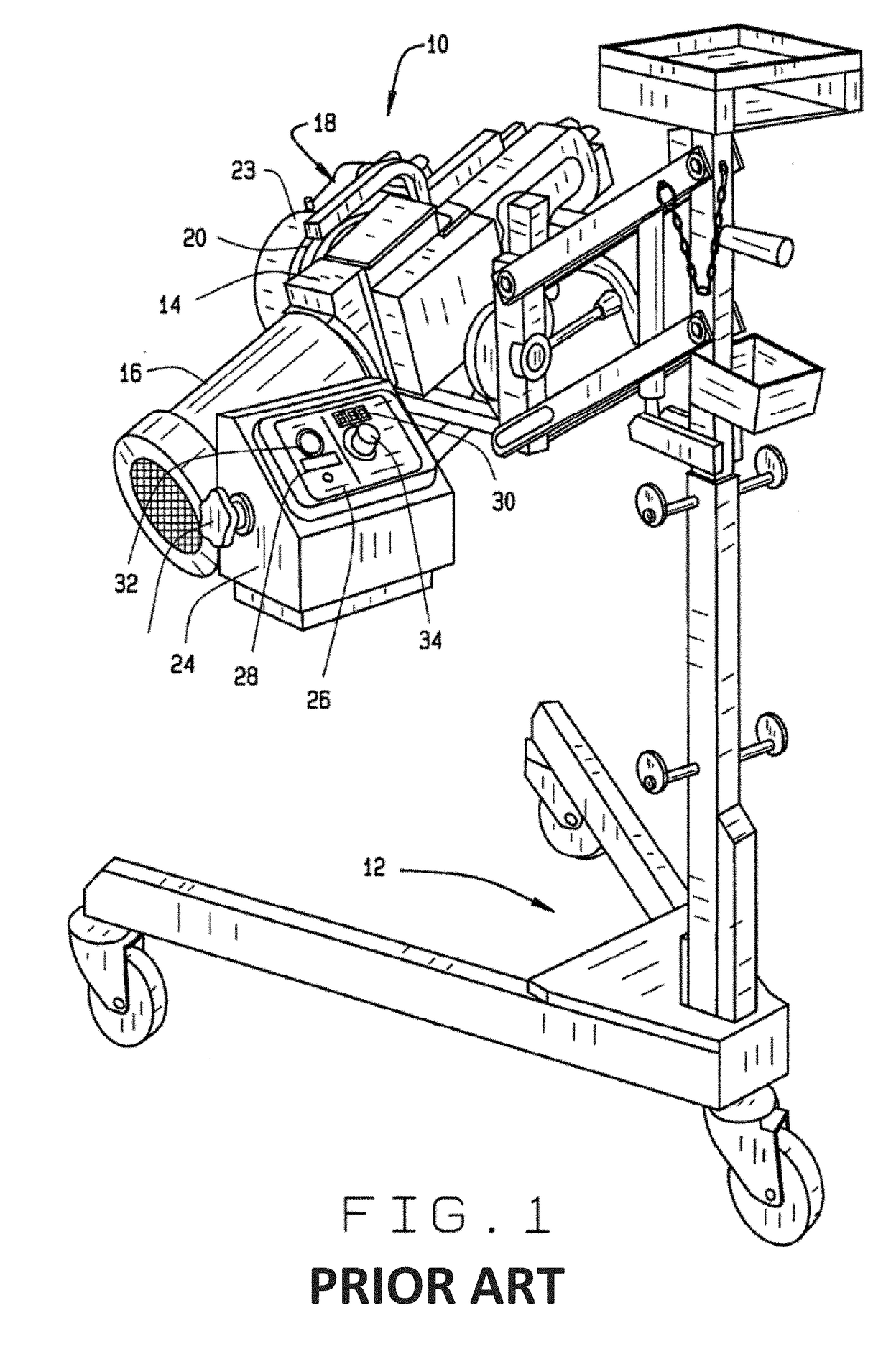
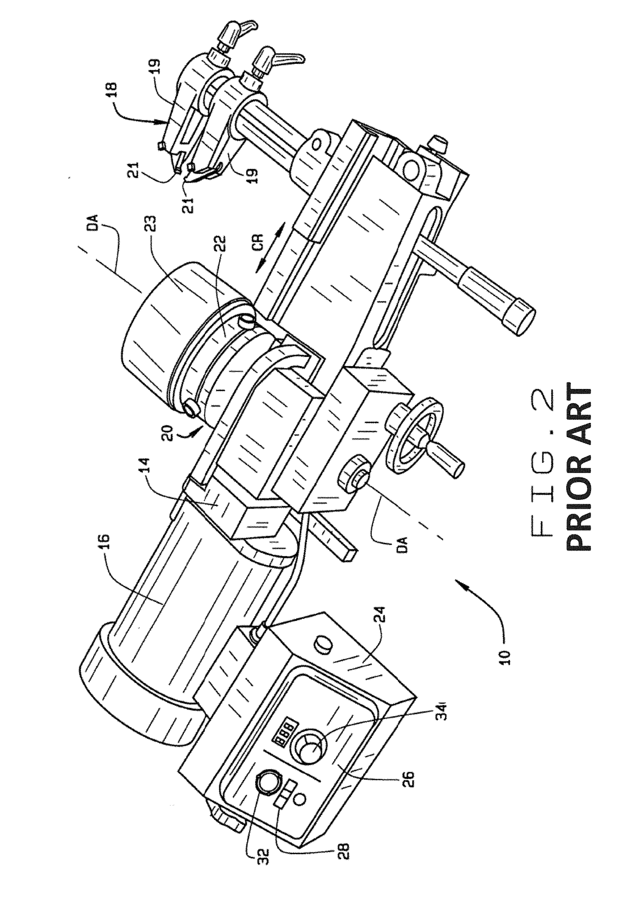
[0035]Referring to FIGS. 1 and 2, a basic on-car brake lathe 10 is shown mounted to a transport trolley 12 for positioning adjacent a vehicle to be serviced (not shown). The on-car brake lathe 10 includes a support structure 14, onto which is mounted a spindle motor 16, which may be a variable speed motor, an adjustable cutting head 18, and an output spindle 20. The spindle motor 16 is coupled to the output spindle 20 through a conventional drive mechanism (not shown) contained within the support structure 14, to rotate the output spindle 20 about a drive axis DA, and to linearly feed the cut...


PUM

PropertyMeasurementUnit
oblique anglesaaaaaaaaaa
DAaaaaaaaaaa
DAaaaaaaaaaa

Abstract

An on-car brake lathe is provided with a runout compensation system configured to monitor the rotational position of a pair of slant discs within an aligning joint of the on-car brake lathe. The system monitors the amount of runout present between the rotating components of the on-car brake lathe and the wheel hub to which the on-car brake lathe is secured. The system calculates the appropriate rotational position for each slant disc within the aligning joint required to impart a necessary adjustment in the wheel coupling rotational axis in order to align the on-car brake lathe with the rotational axis of the wheel hub. Finally, an adjustment mechanism is activated to rotationally drive each slant disc directly to the calculated rotational position with a minimum amount of rotational movement based on the current rotational position of each slant disc and the required calculated rotational positions.

Description

CROSS-REFERENCE TO RELATED APPLICATIONS[0001]The present application is related to, and claims priority from, U.S. Provisional Patent Application Ser. No. 62 / 351,081 filed on Jun. 16, 2016, and which is herein incorporated by reference.STATEMENT REGARDING FEDERALLY SPONSORED RESEARCH[0002]Not Applicable.BACKGROUND OF THE INVENTION[0003]The present invention relates to automotive vehicle brake lathes configured for resurfacing brake rotor components, and in particular, to an improved on-car brake lathe apparatus and a method for compensating for runout between an on-car brake lathe and a vehicle wheel hub to which the on-car brake lathe is secured for a brake rotor resurfacing operation.[0004]One of the main components of a vehicle wheel braking system employing disc brakes are the brake rotors, which provide a solid rotating surface against which the stationary brake friction pads are clamped or compressed to generate a frictional force, slowing the rotational movement of the brake ...

Claims


Application Information

Patent Timeline
Patent Type & Authority Applications(United States)
IPC IPC(8): B23B5/04G01B7/31G01D5/14
CPCB23B5/04G01B7/31G01D5/145B23B2270/48B23B2235/04B23B2260/128B23B2235/21
Inventor NELGNER, WILLIAM JAMESTALBOTT, JEFFREY P.CLASQUIN, JOEL A.
Owner HUNTER ENG
Why Eureka
Try Eureka