X-ray diffractometer
a diffractometer and x-ray technology, applied in the field of parallel beam x-ray diffractometers, can solve the problems of reducing the amount of x-rays considerably, difficult to obtain high-intensity in-plane diffracted x-rays, so as to reduce the width of diffracted x-rays, enhance the position resolution, reduce the width o
- Summary
- Abstract
- Description
- Claims
- Application Information
AI Technical Summary
Benefits of technology
Problems solved by technology
Method used
Image
Examples
first embodiment
of the X-Ray Diffractometer
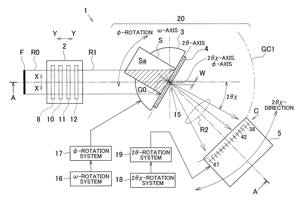
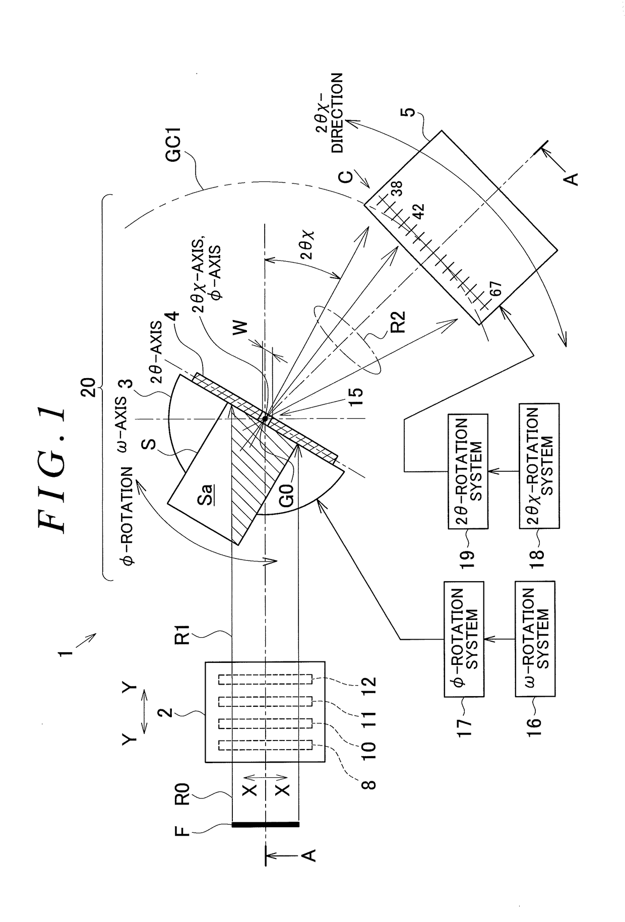
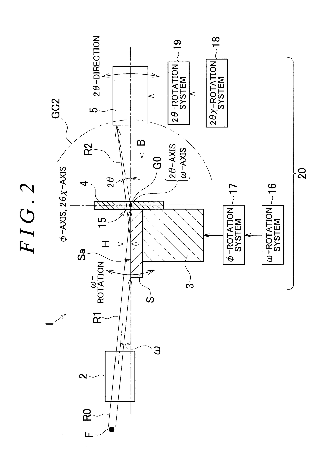
[0081]FIGS. 1 and 2 show an embodiment of an in-plane reciprocal-space mapping apparatus, which is an embodiment of the X-ray diffractometer according to the present invention. FIG. 1 is a plan view of an in-plane reciprocal-space mapping apparatus, and FIG. 2 is a side view along the line A-A of FIG. 1. In FIG. 2, the cross-sectional structure of non-essential portions is omitted.
[0082]The in-plane reciprocal-space mapping apparatus simultaneously performs measurement by in-plane diffraction and measurement by reciprocal-space mapping. Measurement by in-plane diffraction and measurement by reciprocal-space mapping are as follows.
[0083](In-Plane Diffraction Measurement)
[0084]An X-ray diffraction measurement method includes out-of-plane measurement and in-plane measurement depending on the direction of the lattice plane to be measured. Out-of-plane measurement is a technique for evaluating a lattice plane K which is not perpendicular to the surface Sa of th...
second embodiment
of the X-Ray Diffractometer
[0132]FIGS. 6 and 7 show another embodiment of the in-plane reciprocal-space mapping apparatus, which is an embodiment of the X-ray diffractometer according to the present invention. FIG. 6 is a plan view of the in-plane reciprocal-space mapping apparatus, and FIG. 7 is a side view of FIG. 6. The same members and devices shown in FIGS. 6 and 7 as the members and devices shown in FIGS. 1 and 2, respectively, will be referred to with the same reference symbols, and a description thereof is omitted.
[0133]In the embodiment shown in FIGS. 1 and 2, a pinhole member 4, which is a single flat plate member provided with a pinhole 15 as an X-ray passage port, was used as an X-ray shield member. In contrast, in the embodiment shown in FIGS. 6 and 7, a pair of plate members 24a, 24b in which a long slit 25 in the longitudinal direction is formed as an X-ray passage port is used as the X-ray shield member. The plate members 24a, 24b are disposed in a tapered shape (i.e...
third embodiment
of the X-Ray Diffractometer
[0138]FIG. 8 shows an embodiment of the Grazing-Incidence Wide-Angle X-Ray Scattering / Small-Angle X-Ray Scattering Apparatus (GI-WAXS / SAXS Apparatus), which is yet another embodiment of the X-ray diffractometer according to the present invention.
[0139]X-ray Small-Angle Scattering is long-known technique for evaluating the nanometer-scale shapes and sizes. Grazing-Incidence Small-Angle X-Ray Scattering (GI-SAXS) is a known technique for causing X-rays to make almost grazing incidence on the surface of a sample and counting the scattered X-rays that almost graze (i.e., at a low angle) and exit the surface of the sample. Furthermore, Grazing-Incidence Wide-Angle X-Ray Scattering (GI-WAXS) is known as a useful measurement technique for causing X-rays to make almost grazing incidence on the surface of a sample and counting the scattered X-rays that exit into a high-angle area with respect to the surface of the sample.
[0140]GI-SAXS can be implemented by setting ...
PUM
| Property | Measurement | Unit |
|---|---|---|
| critical angle | aaaaa | aaaaa |
| width | aaaaa | aaaaa |
| width | aaaaa | aaaaa |
Abstract
Description
Claims
Application Information
 - R&D
- Intellectual Property
- Life Sciences
- Materials
- Tech Scout
- Unparalleled Data Quality
- Higher Quality Content
- 60% Fewer Hallucinations
Browse by: Latest US Patents, China's latest patents, Technical Efficacy Thesaurus, Application Domain, Technology Topic, Popular Technical Reports.
© 2025 PatSnap. All rights reserved.Legal|Privacy policy|Modern Slavery Act Transparency Statement|Sitemap|About US| Contact US: help@patsnap.com


