Image forming apparatus

a technology of image forming apparatus and forming wire, which is applied in the direction of electrographic process apparatus, instruments, optics, etc., can solve the problems of signal transmission via electric wire, and achieve the effect of reducing the influence of electromagnetic nois

Inactive Publication Date: 2017-12-21
CANON KK
View PDF2 Cites 2 Cited by
  • Summary
  • Abstract
  • Description
  • Claims
  • Application Information

AI Technical Summary

Benefits of technology

[0005]A principal object of the present invention is to provide an image forming apparatus capable of reducing an influence of electromagnetic noise on an electric wire connecting an image reading portion and a controller substrate in a constitution in which a plurality of controller substrates are provided on a side surface of a casing.

Problems solved by technology

However, in such a constitution, an electric wire connecting the image reading portion and the main controller substrate passes through the neighborhood of the additional substrate in some cases, so that there was a liability that a signal transmitted via the electric wire is deteriorated by electromagnetic noise generating from the additional substrate.

Method used


Image

  • Image forming apparatus
  • Image forming apparatus
  • Image forming apparatus

Examples


Embodiment Construction

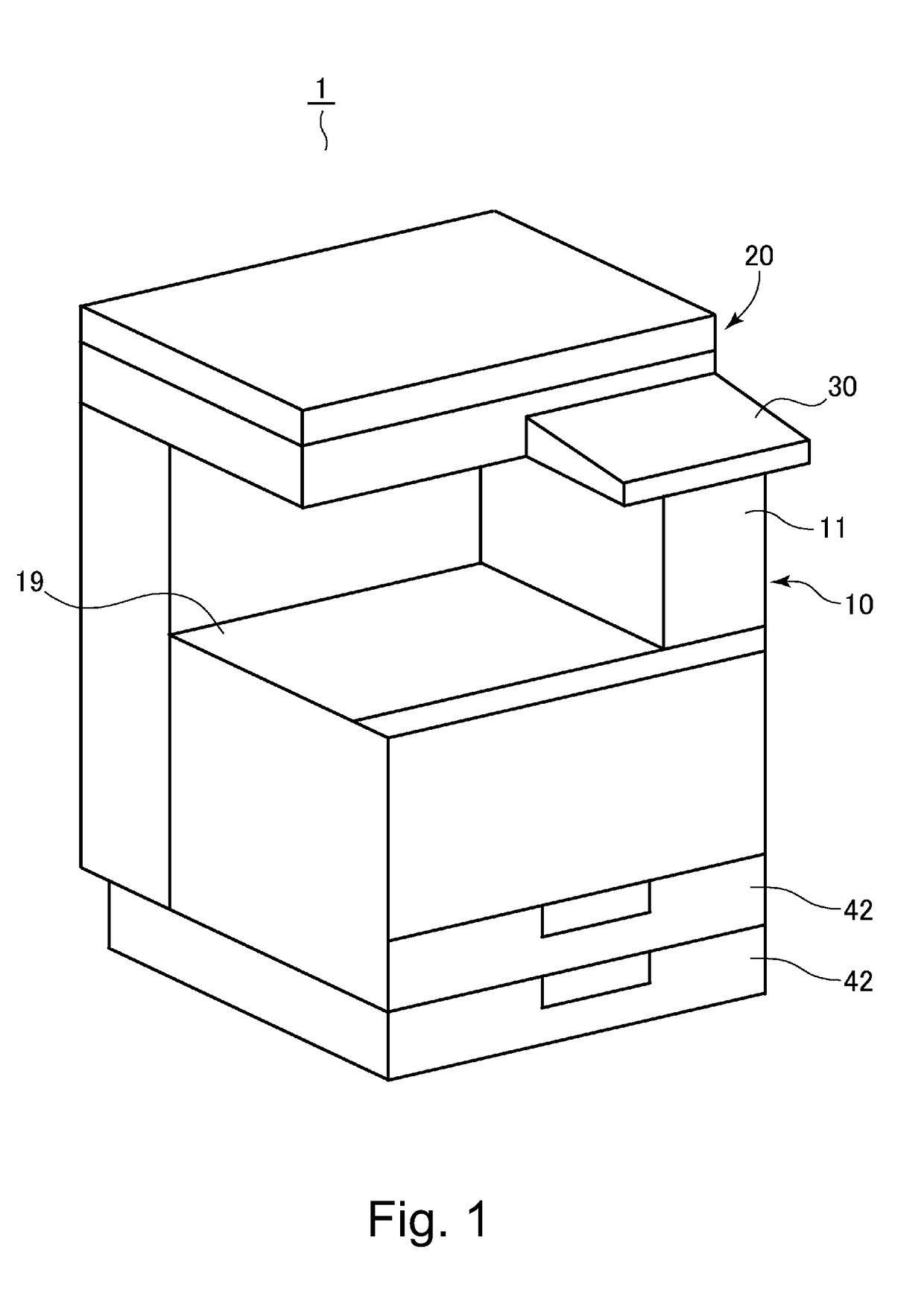
[0014]An image forming apparatus according to the present invention will be described with reference to the drawings. An image forming apparatus 1 shown in FIG. 1 is a full-color laser printer. In the following description, as regards a side (right from side of FIG. 1) where an operating portion 30 is provided on an apparatus main assembly 10, a side surface in the side is a “front surface” and a side surface in a side opposite from the (front surface) side is a “rear surface”. Further, a right-hand side surface of the apparatus main assembly 10 as seen from the front surface side is a “right side surface” and a side surface in a side opposite from the (right side surface) side is a “left side surface”.

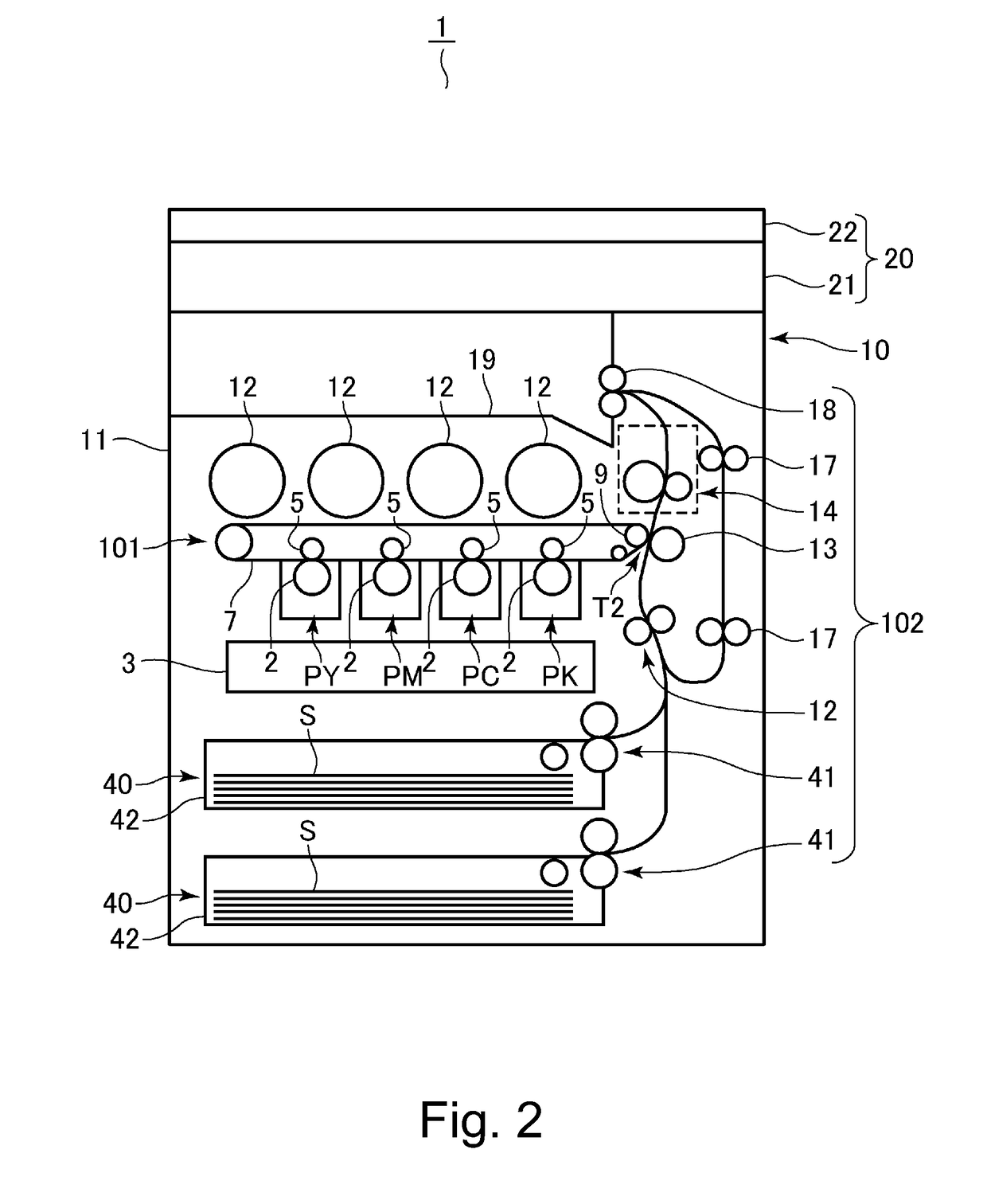
[0015]The image forming apparatus 1 roughly includes the apparatus main assembly 10 and an image reading portion 20 provided on the apparatus main assembly 10. The apparatus main assembly 10 incorporates an image forming portion 101 described later, and form an image on a recording ma...


PUM


Abstract

An image forming apparatus includes an image forming portion, a casing, an image reading portion, a first controller substrate provided on one of side surfaces of the casing, a second controller substrate provided on the side surface, wherein a component mounting surface of the second controller substrate is in a non-overlapping position with a component mounting surface of the first controller substrate, an electric wire configured to connect the first controller portion and the image reading portion, and a shielding member fixed to the casing so as to be provided between the electric wire and the second controller substrate and configured to shield electromagnetic radiation from the second controller substrate toward the electric wire.

Description

FIELD OF THE INVENTION AND RELATED ART[0001]The present invention relates to an image forming apparatus such as a printer, a copying machine, a facsimile machine or a multi-function machine.[0002]Conventionally, in the image forming apparatus, a constitution in which in addition to a main controller substrate for controlling an image forming operation, an auxiliary controller substrate (additional substrate) for imparting a facsimile (FAX) function is capable of being additionally mounted has been known. For example, Japanese Laid-Open Patent Application (JP-A) 2004-85944 discloses a constitution in which a FAX function expansion board is directed connected with an on-board connector of a controlling board for controlling a mechanical operation of the image forming apparatus.[0003]Further, conventionally, an image forming apparatus in which an image reading portion is provided at an upper portion of a casing and in which a scanner function and a printer function are realized in comb...

Claims


Application Information

Patent Timeline
Patent Type & Authority Applications(United States)
IPC IPC(8): G03G15/00G03G21/16
CPCG03G15/5075G03G21/1604G03G15/5025G03G15/80H04N1/00557H04N1/00559H04N1/00885H04N1/00994G03G21/1652
Inventor YOSHINO, DAIJU
Owner CANON KK
Why Eureka
Try Eureka