
Probe spacing element

A technology of probes and components, which is applied in the field of guided wave radar level gauges, can solve complex problems such as installation and removal, and achieve the effects of promoting accurate detection, eliminating reflections, and reducing electromagnetic influence

Inactive Publication Date: 2014-06-11
ROSEMOUNT TANK RADAR
View PDF8 Cites 1 Cited by
  • Summary
  • Abstract
  • Description
  • Claims
  • Application Information

AI Technical Summary

Problems solved by technology

Such an arrangement is complex both for installation and removal, since the entire measuring tube must be disassembled in order to remove the probe

Method used


Image

  • Probe spacing element
  • Probe spacing element
  • Probe spacing element

Examples


Embodiment Construction

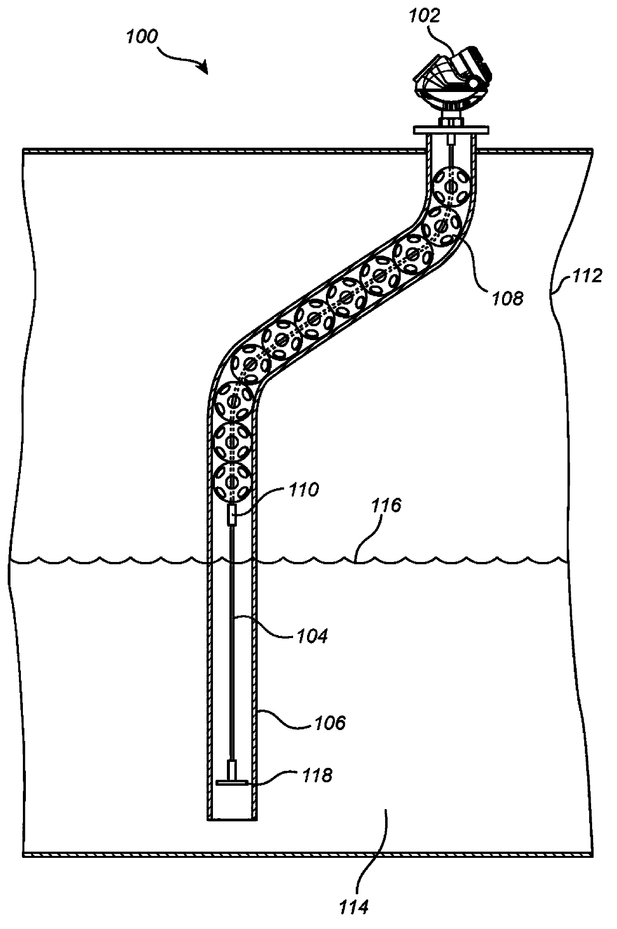
[0045] In the detailed description of the invention, various embodiments of a guided wave radar level gauge system according to the invention are discussed primarily with reference to a radar level gauge system having a single-wire transmission line probe arranged in a conduit. It should be noted that this in no way limits the scope of the invention, which is equally applicable to other types of probes which may be arranged wholly or partly in a catheter, or probes arranged on inclined surfaces, Or free-hanging probes without mechanical support.

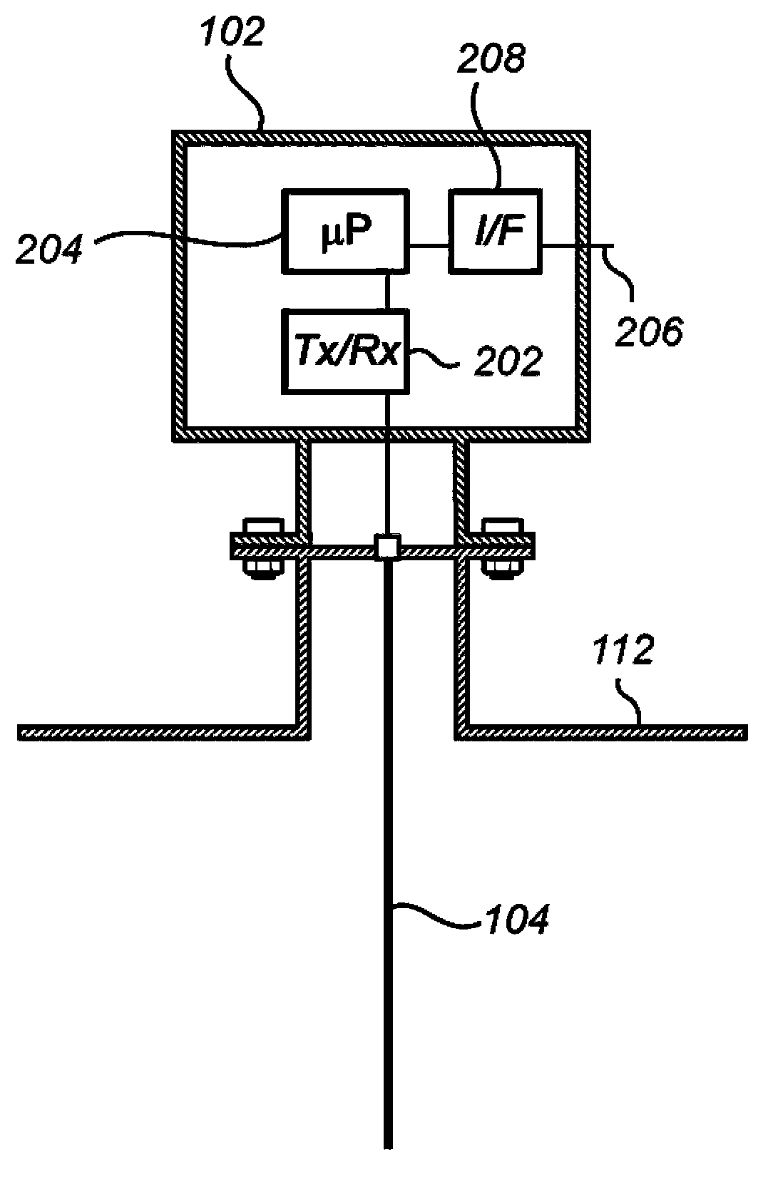
[0046] figure 1 A guided wave radar level gauge system 100 according to an embodiment of the invention is schematically shown, comprising a measurement electronics unit 102 and a probe 104 arranged in a conduit 106 . A plurality of spacer elements 108 are arranged on the probe 104 . The spacer element 108 is prevented from moving down the probe 104 by a locking element 110 arranged on the probe 104 . The locking element 110 may be...


PUM


Abstract

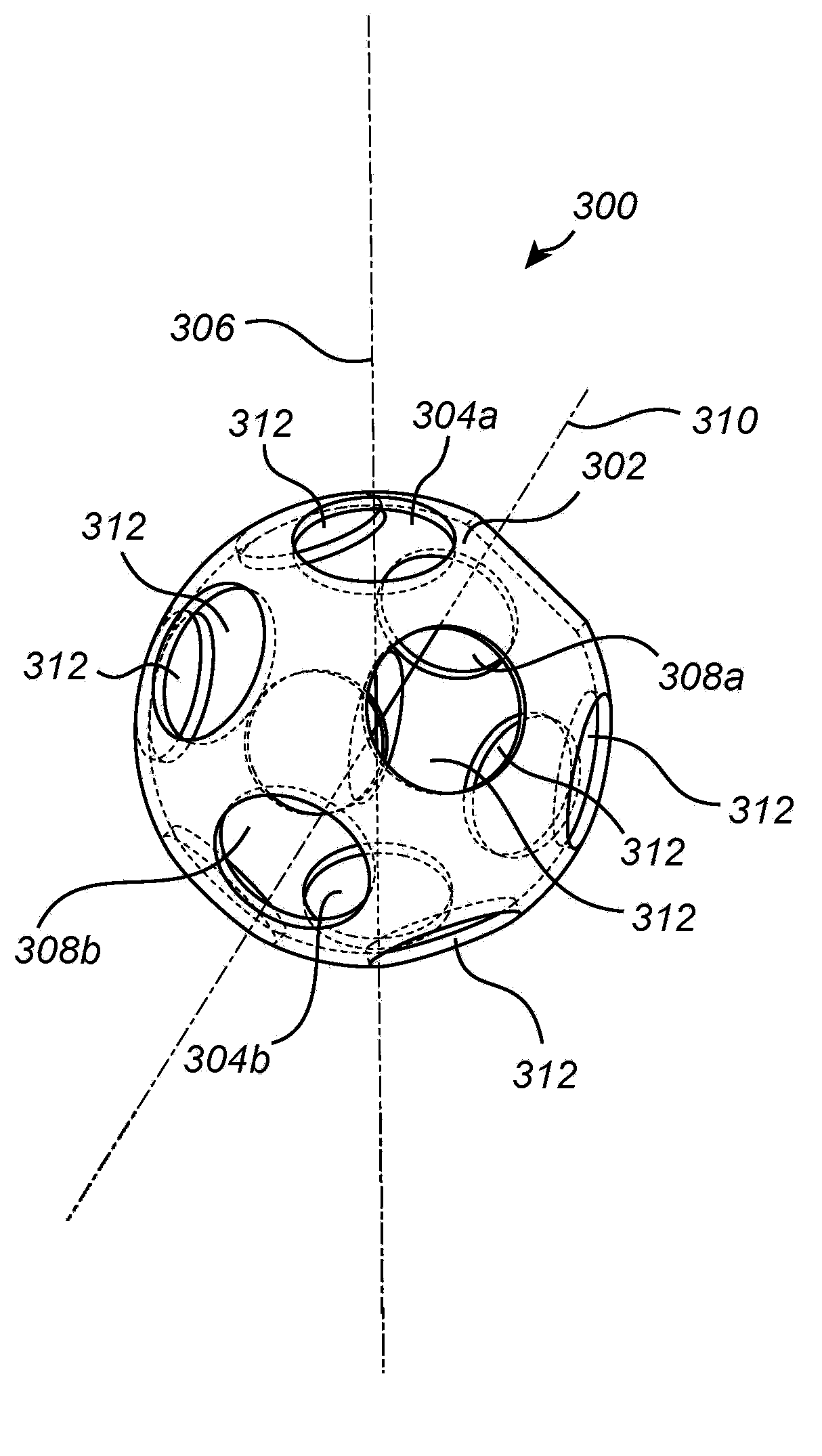
The present invention relates to a guided wave radar level gauge system for determining a filling level of a product contained in a tank. The level gauge system comprises a transceiver for transmitting and receiving electromagnetic signals, a probe extending into the tank and configured to guide the signals towards the surface and to guide reflected signals back to the transceiver, processing circuitry for determining the filing level based on the reflected signals, and a plurality of spacing elements arranged on the probe. Each spacing element comprises a shell structure having an ellipsoidal shape defining an ellipsoidal space, first and second shell openings at first and second locations of the shell, such that a passage through the shell openings defines a passage through the spherical space, wherein the probe extends through the passage, and a plurality of flow openings allowing fluid flow between the exterior and interior of the shell.

Description

technical field [0001] The present invention relates generally to a guided wave radar level gauge for determining the fill level of a product contained in a container, and in particular to such a level gauge including a probe extending into the container. Background technique [0002] Microwave level gauge or radar level gauge (RLG) systems are widely used to determine the fill level of products contained in containers. Radar level gauging is usually carried out by means of non-contact measurement or contact measurement, often called guided wave radar (GWR), in which electromagnetic signals are radiated to the product contained in the container by means of non-contact measurement, by means of Electromagnetic signals are guided into and into the product by means of a probe acting as a waveguide transmission line during tactile measurements. [0003] The probes of the guided wave radar system may be flexible probes such as transmission line probes, cable or wire type probes. ...

Claims


Application Information

Patent Timeline
Patent Type & Authority Applications(China)
IPC IPC(8): G01F23/284G01F23/26
CPCG01S13/08G01F23/284G01S13/88G01S7/02H01P3/10H01Q1/225
Inventor 哈坎·弗雷德里克松
Owner ROSEMOUNT TANK RADAR
Learn More