Charged Particle Beam System and Method of Aberration Correction

Inactive Publication Date: 2017-12-21
JEOL LTD
View PDF2 Cites 5 Cited by
  • Summary
  • Abstract
  • Description
  • Claims
  • Application Information

AI Technical Summary

Benefits of technology

The patent is about a charged particle beam system that reduces phase variations in a charged particle beam, which can improve image resolution. The system introduces fourth order three-lobe aberration and three-fold astigmatism into the sixth order three-lobe aberration that remains after correction of six-fold astigmatism. This reduces the phase variations in the beam and improves image quality. The method of introducing aberration correction is straightforward and easy to implement. Overall, the system and method described in the patent enhance image resolution and improve the quality of charged particle beam systems.

Problems solved by technology

However, if the six-fold astigmatism is corrected, sixth order three-lobe aberration of sixth order geometric aberration cannot be corrected but rather remains as an aberration that limits the range of aberration correction.
This leads to a deterioration of the image resolution.

Method used


Image

  • Charged Particle Beam System and Method of Aberration Correction
  • Charged Particle Beam System and Method of Aberration Correction
  • Charged Particle Beam System and Method of Aberration Correction

Examples


first embodiment

1. First Embodiment

1.1. Configuration of Electron Microscope

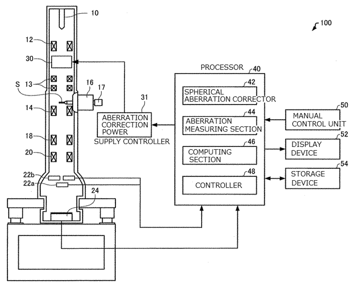
[0045]An electron microscope associated with a first embodiment of the present invention is first described by referring to FIG. 1, which schematically shows the electron microscope, 100.

[0046]The electron microscope 100 is a scanning transmission electron microscope (STEM) equipped with an aberration corrector 30. The scanning transmission electron microscope is an instrument for obtaining a scanning transmission electron microscope (STEM) image by scanning an electron probe (focused ion beam) over a sample S and detecting electrons transmitted through the sample S.

[0047]As shown in FIG. 1, the electron microscope 100 includes an electron source 10, a condenser lens system 12, scan coils 13, an objective lens 14, a sample stage 16, a sample holder 17, an intermediate lens 18, a projector lens 20, STEM detectors 22a, 22b, an imager 24, the aberration corrector 30, a processor 40, a manual control unit 50, a display device 5...

second embodiment

2. Second Embodiment

2.1. Configuration of Electron Microscope

[0110]An electron microscope associated with a second embodiment is next described. Only the differences with the electron microscope 100 associated with the first embodiment are described below; a description of similarities is omitted.

[0111]In the above-described electron microscope 100 associated with the first embodiment, phase variations in the electron beam due to sixth order three-lobe aberration are reduced by introducing fourth order three-lobe aberration. On the other hand, in the electron microscope associated with the second embodiment, phase variations in the electron beam due to sixth order three-lobe aberration are reduced by introducing three-fold astigmatism.

[0112]The electron microscope associated with the second embodiment is identical in configuration to the electron microscope 100 associated with the first embodiment shown in FIG. 1 and consequently its description and illustration is omitted.

[0113]In ...

third embodiment

3. Third Embodiment

3.1. Configuration of Electron Microscope

[0135]An electron microscope associated with a third embodiment is next described. Only differences with the above-described electron microscopes associated with the first and second embodiments, respectively, are described below; a description of similarities is omitted.

[0136]In the above-described electron microscope 100 associated with the first embodiment, phase variations in the electron beam due to sixth order three-lobe aberration are reduced by introducing fourth order three-lobe aberration. Furthermore, in the electron microscope associated with the second embodiment, phase variations in the electron beam due to sixth order three-lobe aberration are reduced by introducing three-fold astigmatism.

[0137]On the other hand, in the electron microscope associated with the third embodiment, phase variations in the electron beam due to sixth order three-lobe aberration are reduced by introducing fourth order three-lobe aber...


PUM


Abstract

There is provided a charged particle beam system for reducing phase variations in a charged particle beam due to sixth order three-lobe aberration. The charged particle beam system (100) is equipped with an aberration corrector (30) for correcting aberrations in the optical system, and includes: an aberration measuring section (44) for measuring sixth order three-lobe aberration of sixth order geometric aberration, a computing section (46) for computing the magnitude of at least one of fourth order three-lobe aberration of fourth order geometric aberration and three-fold astigmatism of second order geometric aberration for reducing phase variations in the charged particle beam due to the sixth order three-lobe aberration on the basis of the measured sixth order three-lobe aberration, and a controller (48) for controlling the aberration corrector (30) to produce at least one of the fourth order three-lobe aberration and the three-fold astigmatism on the basis of the computed magnitude.

Description

BACKGROUND OF THE INVENTIONField of the Invention[0001]The present invention relates to a charged particle beam system and method of aberration correction.Description of Related Art[0002]In transmission electron microscopy, aberration correction is a technique that is important in achieving high-resolution imaging.[0003]For example, H. Rose, Optik, vol. 85 (1990), pp. 19-24, H. Haider et al., Nature, vol. 392 (1998), pp. 768-769, and H. Muller et al., Microsc., Microanal. 12, pp. 442-455 (2006) disclose two-stage, three-fold field spherical aberration correctors in each of which there are arranged two stages of hexapole elements. In these known spherical aberration correctors, positive spherical aberration in an objective lens is corrected by negative spherical aberration produced by hexapole elements. In two-stage, three-fold field spherical aberration correctors, six-fold astigmatism of the fifth-order geometric aberration normally remains as a dominant aberration. However, the si...

Claims


Application Information

Patent Timeline
IPC IPC(8): H01J37/153H01J37/28
CPCH01J37/28H01J37/153H01J2237/1534H01J2237/2802H01J2237/1532
Inventor MORISHITA, SHIGEYUKI
Owner JEOL LTD
Why Eureka
Try Eureka